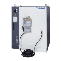
1 Equipment Configuration
1.1 Arrangement of Units and Circuit Boards
1-1
1 Equipment Configuration
The DX200 is comprised of individual units and modules (circuit boards).
Malfunctioning components can generally be easily repaired after a failure
by replacing a unit or a module. This section explains the configuration of
the DX200 equipment.
1.1 Arrangement of Units and Circuit Boards
1.1.1 Arrangement
The arrangements of units and circuit boards in small-capacity, medium-
capacity, and large-capacity DX200s are shown.
1.1.1.1 Small-Capacity DX200 Controller
Fig. 1-1: Configuration for Small Capacity
For the models not described in this manual, refer to the
DX200 instructions supplement.
Brake control
circuit board
Amplifier module
CPU unit
Machine safety I/O
logic circuit board
Machine safety
CPU circuit board
Machine safety terminal
block circuit board
Universal I/O
circuit board
4715MS-22T-B50-B00
Regenerative resistor
Back View
Breaker
Emergency stop
button
Front View
Backside duct fan
Robot I/F
circuit board
Major axes control
circuit board
Inside Controller
Inside Controller
Front Door
Inside View
Converter
Capacitor module
(Refer to the table 5-3)
Sectional View A-A'
SMVK500W6R0J A6103
Control power
supply unit
Power ON unit
JZNC-YPS21-E
JZNC-YRK21-1E
SRDA-COA30A21B-E
NF32-SVF
JANCD-YIF01-2E
JZRCR-YPU51-1
4715MS-22T-B50-B00
Internal air circulation fan
HW1B-V404R
SRDA-CUA662AA
JANCD-YFC22-E
JANCD-YIO21-E
JANCD-YSF22 -E
JANCD-YSF21-E
JANCD-YBK21-3E
SRDA-EAXA21A
A
A
Model DX200
MA1440 ERER-MA1440/MH12-A00
MH12

 Loading...


