u
Using the DO-A3 Option for Additional Lag Pumps
The drive comes standard with three output relays capable of controlling three lag pumps. With the addition of a DO-A3 card
installed in the drive, two additional lag pumps can be controlled bring the total to five lag pumps.
n
Required Control Wiring
Install the DO-A3 option card on the CN5-A, CN5-B, or CN5-C option connector on the drive. Refer to the DO-A3 Installation
Manual packaged with the option for installation and wiring instructions. The option card has two relay outputs on terminal
block 1 (TB1) and 6 photocoupler outputs on terminal block 2 (TB2). the drive uses only the relay outputs on terminal block
1.
n
Start Up Procedure for Controlling a Lead Pump plus Five Lag Pumps
1.
Install and wire the DO-A3 as indicated in the option installation manual.
2.
Set all other parameters required for the application such as PI control loop, sleep, motor, and I/O parameters.
3.
Program drive parameters with the values shown in Table 4.7 to correctly control each lag pump.
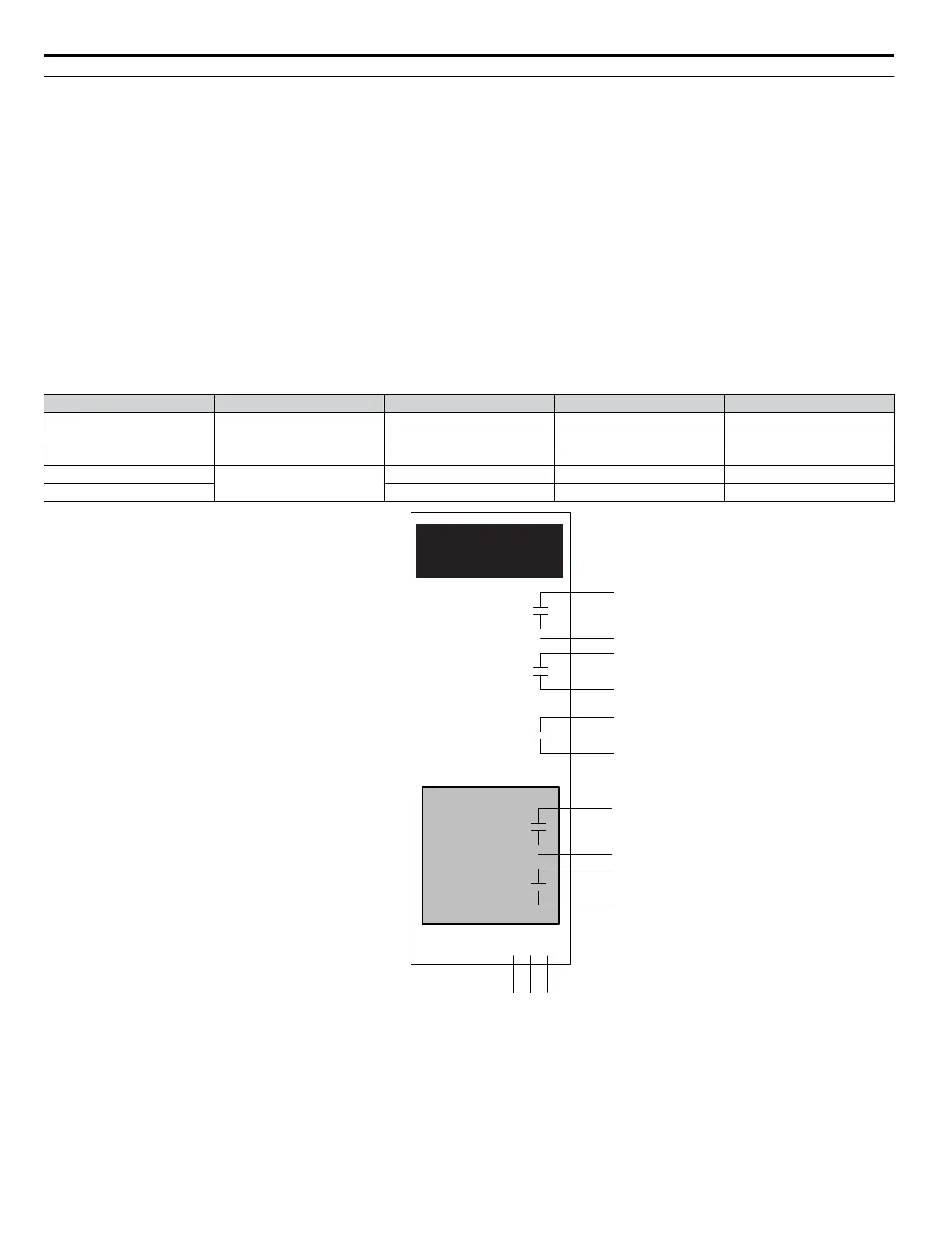
Table 4.7 Lag Pump Settings
Lag Pump Number Terminal Location Terminal Numbers Parameter Setting
1
Control Board
M1-M2 H2-01 80
2 M3-M4 H2-02 81
3 MD-MF H2-03 82
4
DO-A3 Option
M1-M2 F5-07 83
5 M3-M4 F5-08 84
Pressure
Feedback
H3-09 = B
(PID Feedback)
A2
P1-01 = 1
(Contactor Multiplex)
M1
M2
LAG
PUMP 1
H2-01 = 80
M3
M4
LAG
PUMP 2
H2-02 = 81
MD
MF
LAG
PUMP 3
H2-03 = 82
M1
M2
LAG
PUMP 4
F5-07 = 83
M3
M4
LAG
PUMP 5
F5-08 = 84
DO-A3
F5-09 = 2
VU W
LEAD PUMP 1
Drive
Figure 4.16 Controlling Five Lag Pumps with DO-A3 Option
4.6 iQpump Presets and Functions
178
YASKAWA TOEP YAIP1W 01F YASKAWA AC Drive - iQpump1000 User Manual