No.
(Addr.
Hex)
Name LCD Display Description Values Page
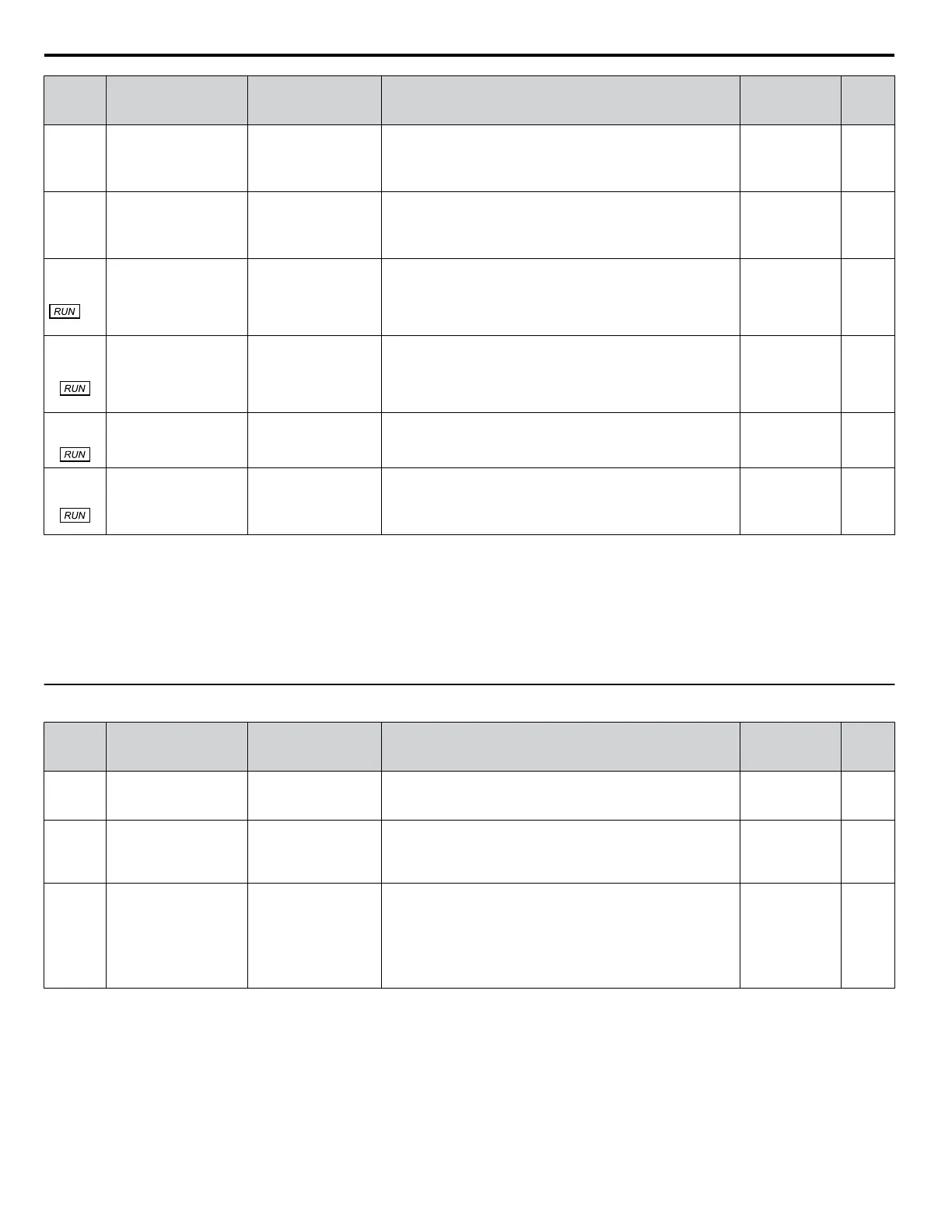
P2-13
(0C70)
Setpoint Compensation Setpoint Comp.
Allows for the software to automatically compensate the
setpoint in the event of excessive cycling.
Default: 0.0 PSI
<3>
Min.: 0.0
Max.: 6000.0
–
P2-14
(0C71)
Maximum Setpoint
Compensation
Max. SP Comp.
Sets the maximum allowed setpoint compensation for over-
cycling function.
Default: 0.0 PSI
<3>
Min.: 0.0
Max.: 6000.0
–
P2-15
(0C72)
<4>
Sleep AUTO -> Off
Selection
Sleep AUTO->Off
0: Disabled
1: Enabled
Enabling this parameter activates Sleep if the P1-04 Start Level
is set to 0 and switches the drive to OFF mode when called to
Sleep.
0: Disabled
1: Enabled
Default: 0
Range: 0, 1
234
P2-23
(0C7A)
Anti-No-Flow
Bandwidth
ANF Bandwidth
Sets the amount of PI error bandwidth used to detect the Anti-
No-Flow condition.
Avoid setting this parameter value too high, as operation may
become unstable.
Setting this parameter to 0.00 will disable the function.
Default: 0.40%
Min.: 0.00
Max.: 2.00
–
P2-24
(0C7B)
Anti-No-Flow
Detection Time
ANF Det. Time
Sets the time delay before the drive starts the increased
deceleration rate after Anti-No-Flow is detected.
Default: 10.0 s
Min.: 1.0
Max.: 60.0
–
P2-25
(0C7C)
Anti-No-Flow Release
Level
ANF Release Lvl
Sets the amount below the setpoint which the feedback must
drop to disengage the Anti-No-Flow and return to normal PI
operation.
Default: 3.0 PSI
<3>
Min.: 0.0
Max.: 100.0
–
<1> Display units vary depending on the setting for P2-01, Sleep Level Type. When P2-01 is set to 0, the display units are “Hz”; setting 1 is “A”; setting
2 is P1-02 Selection; setting 3 is “RPM”; setting 4 is P6-04 selection.
<2> Display units vary depending on the setting for P2-01, Sleep Level Type. When P2-01 is set to 0, 1, 2, or 4, the display units are “Hz”; setting 3 is
“RPM”.
<3> Unit is determined by P1-02, System Units, setting.
<4> Available in drive software versions PRG: 8552 and later. Changes during Run in drive software versions PRG: 8554 and later. Not available in
drive models 4A0930 and 4A1200.
u
P3: Contactor Multiplexing
No.
(Addr.
Hex)
Name LCD Display Description Values Page
P3-00
(0CC7)
Number of Lag Pumps Num of Lag Pumps
Sets the number of lag pumps present. Default: 1
Min.: 1
Max.: 5
234
P3-01
(0CC8)
Add Pump Control
Add Pump Control
0: Output Frequency
1: Feedback
2: Feedback + Fout
Selects the method for adding contactor pumps to the system.
0: Output frequency (Uses P3-03 and P3-05)
1: Feedback (Uses P3-04 and P3-05)
2: Feedback + Fout (Uses P3-03, P3-04, and P3-05)
Default: 0
Range: 0 to 2
–
P3-02
(0CC9)
Shutdown Pump
Control
Shutdown Pump Ctl
0: Output Frequency
1: Feedback
2: Feedback + Fout
Selects the method for removing contactor pumps from the
system.
0: Output frequency (Uses P3-09, P3-50 P3-60, P3-70, P3-80,
and P3-90)
1: Feedback (Uses P3-08 and P3-09)
2: Feedback + Fout (Uses P3-08, P3-09, P3-50, P3-60, P3-70,
P3-80, and P3-90)
Default: 0
Range: 0 to 2
–
B.12 P: Pump Parameters
406
YASKAWA TOEP YAIP1W 01F YASKAWA AC Drive - iQpump1000 User Manual

 Loading...


