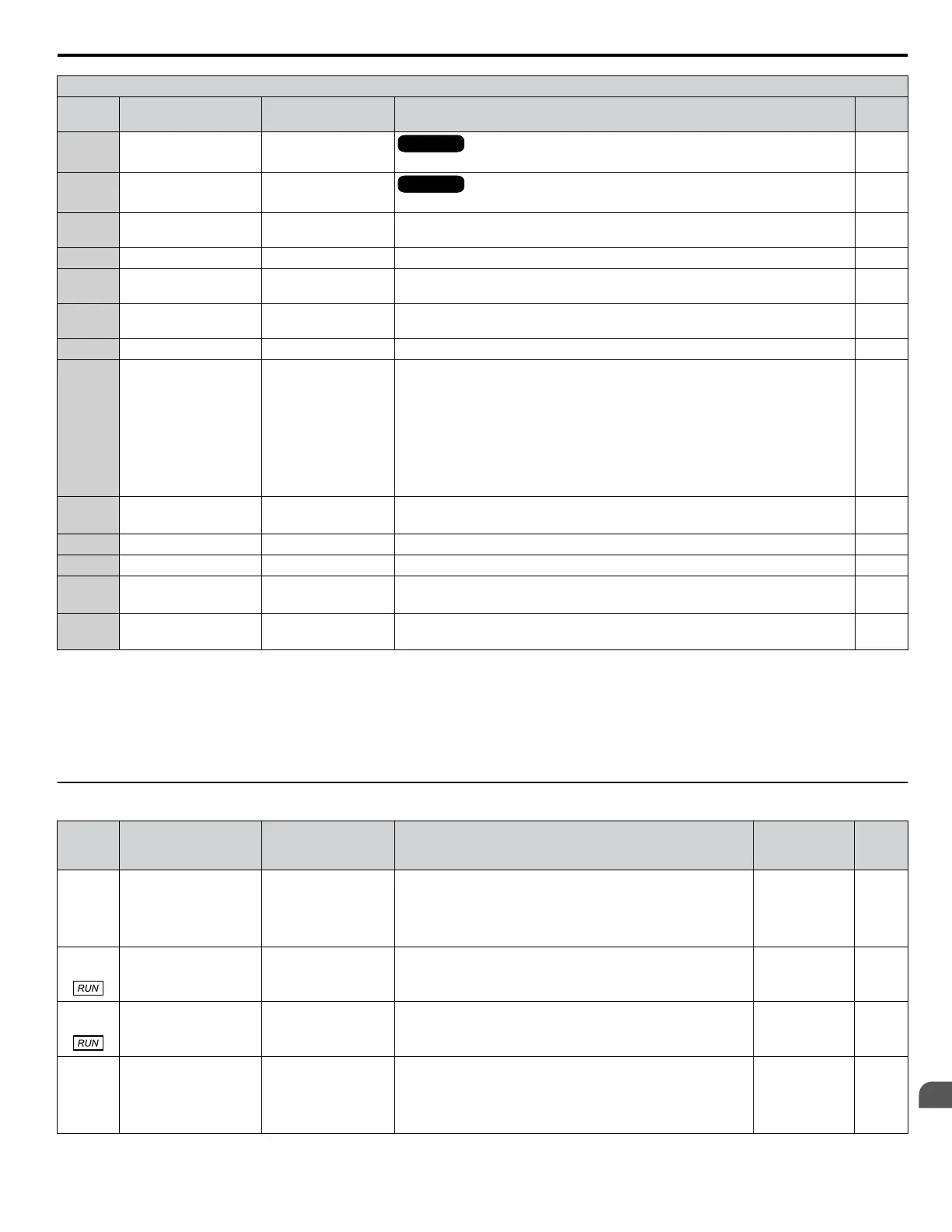
H3 Multi-Function Analog Input Settings
H3-oo
Setting
Function LCD Display Description Page
12
Regenerative torque
limit
Regen Torq Limit
OLVOLVOLVOLV
10 V = Motor rated torque
–
15 General torque limit Torque Limit
OLVOLVOLVOLV
10 V = Motor rated torque
–
16
Differential PID
feedback
PID Feedback 2
10 V = 100%
–
1F Through mode Not Used Set this value when using the terminal in the pass-through mode. –
20
HAND Frequency
Reference
Hand Freq. Ref. Full scale: Max. frequency (E1-04) –
21
Geothermal
Temperature
Geothermal Temp
Full scale: Q2-02 = 10 V (or 20 mA), Q2-01 = 0 V (or 4 mA)
This input is internally limited to -110.0 °F to +320.0 °F after gain and bias.
–
22 Flow Meter Flow Meter Full scale: P6-01 –
23
Water Level or Suction
Input
WaterLvl/Suction
When Water Level Control is enabled (Q4-01 = 1):
0 V or 4 mA = 0 (ft)
10 V or 20 mA = Q4-02 (PSI) * 2.308 ft/PSI OR
When Suction Pressure Control is enabled (Q5-01 = 1)
<2>
0 V or 4 mA = 9 (PSI)
10 V or 20 mA = Q5-02 (PSI) OR
When Vacuum Control is enabled (Q5-01 = 2)
<3>
0 V or 4 mA = 0 (”Hg)
10 V or 20 mA = Q5-02 (”Hg)
–
24
<1>
PI Feedback Backup PI FdBack Backup Full scale: FB Device Scaling (P1-03) –
25 Secondary PI Setpoint PI2 Setpoint 10 V = S3-02 (maximum output frequency) –
26 Secondary PI Feedback PI2 Feedback 10 V = S3-02 (maximum output frequency) –
27
<4>
PI Auxiliary Feedback
Level
PI Aux FB Level
0 V or 4 mA = 0 (unit based on Q6-22)
10 V or 2 0mA = Q6-02 (unit based on Q6-22)
–
28
<4>
Differential PI
Feedback
Diff PI Feedback Full scale: FB Device Scaling (P1-03) –
<1> Available in drive software versions PRG: 8551 and later.
<2> When Pressure Control is enabled (Q5-01 = 1), the action of the analog input is normal. A higher voltage or current on the input causes a higher
pressure to be read in the drive.
<3> When Vacuum Control is enabled (Q5-01 = 2), the action of the analog input is reversed. A higher voltage or current on the input causes a lower
pressure (or higher level of vacuum) to be read in the drive.
<4> Available in drive software versions PRG: 8552 and later. Not available in drive models 4A0930 and 4A1200.
u
H4: Analog Outputs
No.
(Addr.
Hex)
Name LCD Display Description Values Page
H4-01
(041D)
Multi-Function Analog
Output Terminal FM
Monitor Selection
Term FM FuncSel
Selects the data to be output through multi-function analog
output terminal FM.
Set the desired monitor parameter to the digits available in
Uo-oo.
For example, enter “103” for U1-03.
Default: 102
Range: 000 to
999
227
H4-02
(041E)
Multi-Function Analog
Output Terminal FM
Gain
Terminal FM Gain
Sets the signal level at terminal FM that is equal to 100% of the
selected monitor value.
Default: 100.0%
Min.: -999.9
Max.: 999.9
228
H4-03
(041F)
Multi-Function Analog
Output Terminal FM
Bias
Terminal FM Bias
Sets the signal level at terminal FM that is equal to 0% of the
selected monitor value.
Default: 0.0%
Min.: -999.9
Max.: 999.9
228
H4-04
(0420)
Multi-Function Analog
Output Terminal AM
Monitor Selection
Terminal AM Sel
Selects the data to be output through multi-function analog
output terminal AM.
Set the desired monitor parameter to the digits available in
Uo-oo.
For example, enter “103” for U1-03.
Default: 103
Range: 000 to
999
227
B.8 H Parameters: Multi-Function Terminals
YASKAWA TOEP YAIP1W 01F YASKAWA AC Drive - iQpump1000 User Manual
385
B
Parameter List