5 Operation
5.4.2 Clear Signal Setting
5-34
5.4.2 Clear Signal Setting
The clear input signal sets the error counter in the multi-winding drive unit to zero.
(1) Connecting the Clear Signal
(2) Clear Input Signal Form
Set the clear input signal form using Pn200.1.
The following items will be changed in the multi-winding drive unit after the error counter has been reset to
zero.
• The error counter in the multi-winding drive unit is set to 0.
• The position loop operation is disabled.
Note: Holding the clear status may cause the servolock to stop functioning and the servomotor to rotate slowly due to drift
in the speed loop.
Pulse Width of Clear Signal
When parameter Pn200.1 is set to 0 or 2, the width of the clear signal must be at least 250 μs to reset the error
counter.
When parameter Pn200.1 is set to 1 or 3, the width of the clear signal must be at least 20 μs to reset the error
counter.
(3) Clear Operation
This parameter determines when the position error should be set to zero according to the condition of the
multi-winding drive unit. Any of three clearing modes can be selected with Pn200.2.
Type Signal Name Connector Pin Number Name
Input
CLR CN1-15
Clear input
/CLR CN1-14
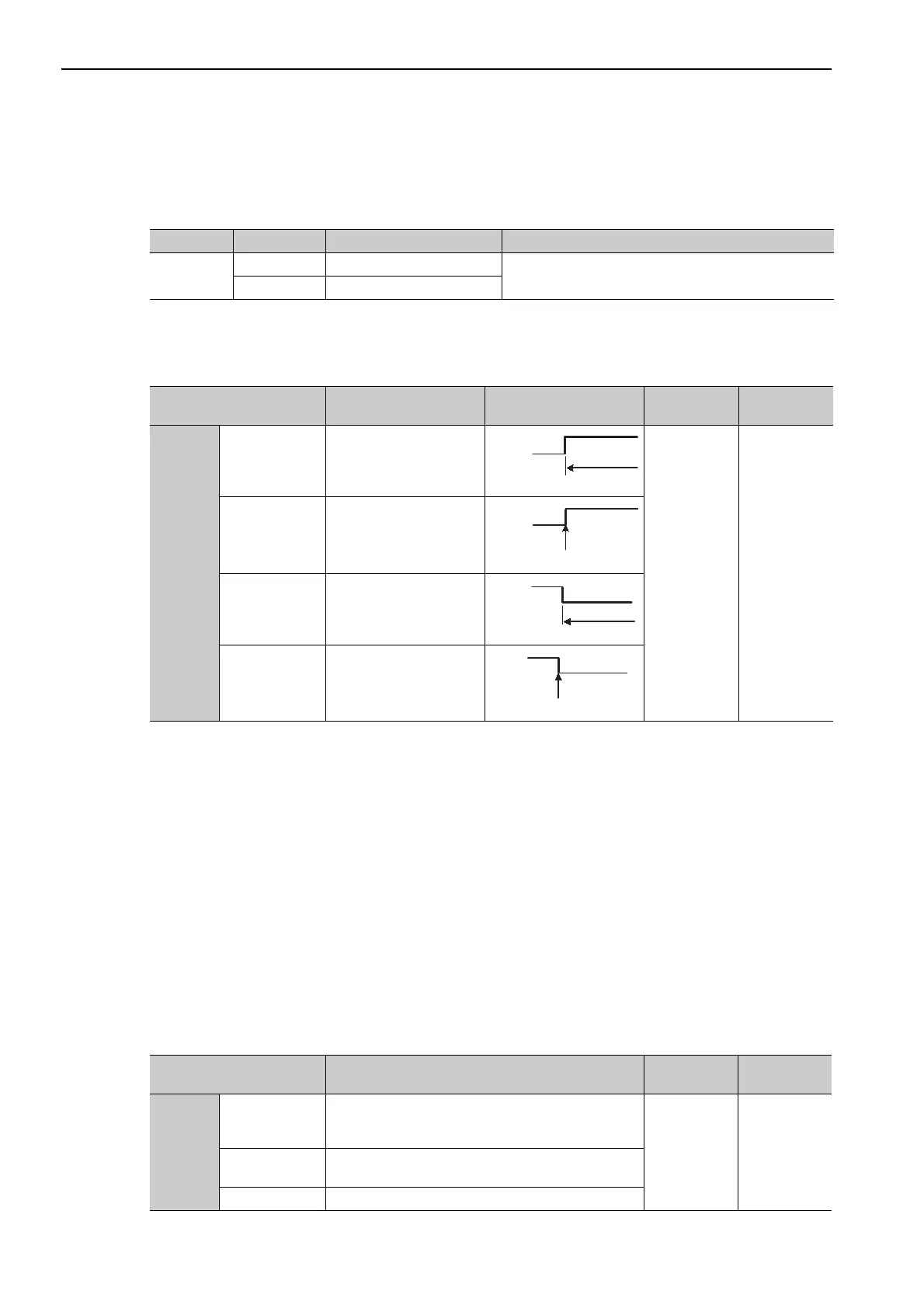
Parameter Description Clear Timing
When
Enabled
Classification
Pn200
n.0
[Factory setting]
Clears at ON.
Position errors do not
accumulate while the sig-
nal is ON.
After restart Setup
n.1 Clears at the rising edge.
n.2
Clears at OFF.
Position errors do not
accumulate while the sig-
nal is OFF.
n.3 Clears at the falling edge.
ON
Clears here just once.
CLR
(CN1-15)
OFF.
CLR
(CN1-15)
Clears at
OFF
Clears here just once.
CLR
(CN1-15)
Parameter Description
When
Enabled
Classification
Pn200
n.0
[Factory setting]
Sets the position error to zero during a baseblock when
an alarm occurs or when the servo ON signal (/S-ON)
turns OFF.
After restart Setup
n.1
Does not set the error counter to zero. Clears the posi-
tion error only with the CLR signal.
n.2 Sets the position error to zero when an alarm occurs.

 Loading...


