6.7 Compatible Adjustment Function
6-51
6.7.6 Torque Reference Filter
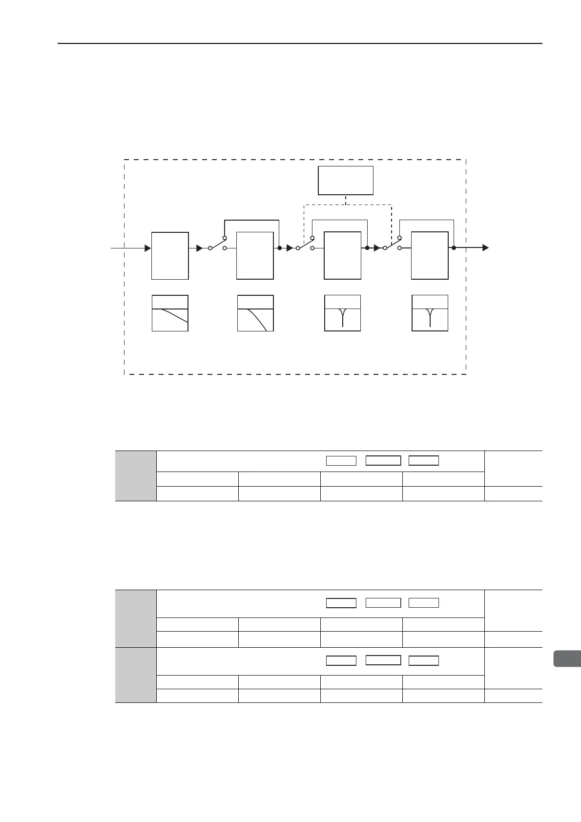
As shown in the following diagram, the torque reference filter contains first order lag filter and notch filters
arrayed in series, and each filter operates independently. The notch filters can be enabled and disabled with the
Pn408.
(1) Torque Reference Filter
If you suspect that machine vibration is being caused by the servo drive, try adjusting the filter time constants
with Pn401. This may stop the vibration. The lower the value, the better the response will be, but there may be
a limit that depends on the machine conditions.
Torque
Reference Filter Setting Guide
Use the speed loop gain (Pn100 [Hz]) and the torque filter time constant (Pn401 [ms]) to set the torque refer-
ence filter.
Adjusted value for stable control: Pn401 [ms] ≤ 1000/ (2π × Pn100 [Hz] × 4)
Critical gains: Pn401 [ms] < 1000/ (2π × Pn100 [Hz] × 1)
∗
The filter is disabled if 5000 is set.
Torque
reference
before
filtering
Torque Related
Function Switch
Pn408
Notch filter Notch filter
First order lag filter
Torque
reference
after
filtering
Second order lag filter
2nd
Notch
Filter
(Pn40C,
Pn40D, and
Pn40E)
1st Notch
Filter
(Pn409,
Pn40A,
and Pn40B)
* The 2nd torque reference filter is enabled when Pn40F is set to a value less than
5000 and disabled when Pn40F is set to 5000 (factory setting).
*
Torque
Reference
Filter
(Pn401)
2nd
Torque
Reference
Filter
(Pn40F,
Pn410)
Pn401
Torque Reference Filter Time Constant
Classification
Setting Range Setting Unit Factory Setting When Enabled
0 to 65535 0.01 ms 100 Immediately Tuning
Torque
Pn40F
2nd Step 2nd Torque Reference Filter
Frequency
Classification
Setting Range Setting Unit Factory Setting When Enabled
100 to 5000 1 Hz
5000
*
Immediately Tuning
Pn410
2nd Step 2nd
Torque
Reference Filter
Q Value
Classification
Setting Range Setting Unit Factory Setting When Enabled
50 to 100 0.01 50 Immediately Tuning
Torque
Torque

 Loading...


