5.6 Internal Set Speed Control
5-49
5.6 Internal Set Speed Control
This section describes operation using speed control with the internal set speeds.
This function enables an operation to be executed at a controlled speed. The speed and direction are selected in
accordance with a combination of input signals from an external source. Servomotor speed settings are made
in advance using the parameters in the multi-winding drive unit. Because the speed is controlled with a param-
eter in the multi-winding drive unit, an external pulse generator or a reference generator that controls speed is
not needed.
∗ When using the external input signal pins as factory settings, the functions of /P-CON, /P-CL, and /N-CL change to the
functions of /SPD-D, /SPD-A, and /SPD-B, respectively.
5.6.1 Basic Settings for Speed Control with an Internal Set Speed
This section describes the basic settings for the internal set speeds.
(1) Signal Setting
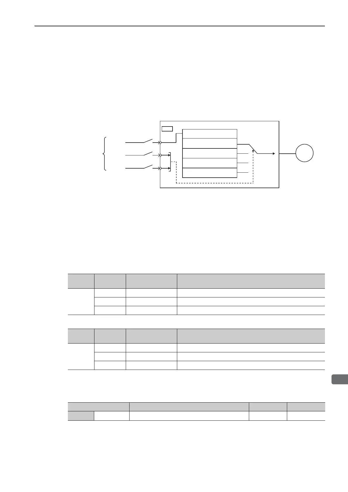
The following input signals are used to switch the operating speed.
Factory-set Input Signal Allocations: /P-CON, /P-CL, and /N-CL
Changing Input Signal Allocations: /SPD-D, /SPD-A, and /SPD-B
(2) Parameter Setting
Select the speed control with an internal set speed with Pn000.1.
41
45
46
Pn301
Pn302
Pn303
M
/
P-CON ( / SPD-D)
/
P-CL ( / SPD-A)
/
N-CL ( / SPD-B)
CN1
Stops (Internal speed 0)
Multi-winding drive system
Parameters for internal set speed
Motor rotation direction
(Forward/Reverse)
Speed
reference
Servomotor
Contact inputs*
Type
Signal
Name
Connector
Pin Number
Meaning
Input
/P-CON CN1-41 Switches the servomotor rotation direction.
/P-CL CN1-45 Selects the internal set speed.
/N-CL CN1-46 Selects the internal set speed.
Type
Signal
Name
Connector
Pin Number
Meaning
Input
/SPD-D CN1-41 Switches the servomotor rotation direction.
/SPD-A CN1-45 Selects the internal set speed.
/SPD-B CN1-46 Selects the internal set speed.
Parameter Meaning When Enabled Classification
Pn000
n.
3
Internal set speed control After restart Setup

 Loading...


