iii
About this Manual
This manual describes information required for designing, testing, adjusting, and maintaining large-capacity
models of servo systems in the Σ-V series.
Keep this manual in a location where it can be accessed for reference whenever required. Manuals outlined on
the following page must also be used as required by the application.
Description of Technical Terms
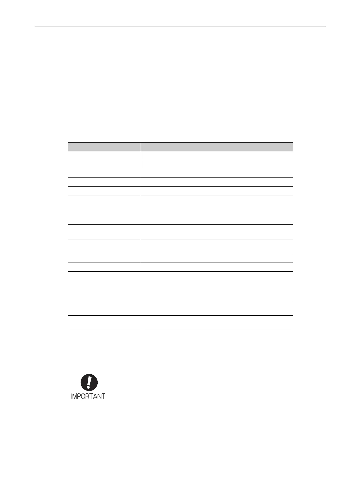
The following table shows the meanings of terms used in this manual.
IMPORTANT Explanations
The following icon is displayed for explanations requiring special attention.
Term Meaning
Servomotor A Σ-V-series SGMVV servomotor
Multi-winding drive unit A Σ-V-series JUSP-MDD multi-winding drive unit
SERVOPACK A Σ-V-series SGDV-J servo amplifier
Converter A Σ-V-series SGDV-COA converter
Servo Drive A set that includes a servomotor, a SERVOPACK, and a converter
Multi-winding drive system
A set that includes a servomotors, multi-winding drive unit, SERVO-
PACK, and converter
Servo System
A servo control system that includes the combination of a servo drive
with a host controller and peripheral devices
Analog pulse model
A multi-winding drive unit with an analog voltage or pulse train refer-
ence interface
M-II model
A multi-winding drive unit with a MECHATROLINK-II communica-
tions reference interface
Servo ON Power to motor ON
Servo OFF Power to motor OFF
Base Block (BB)
Power supply to motor is turned OFF by shutting off the base current
to the power transistor in the SERVOPACK.
Main circuit
The circuit related to the main circuit power supply and control power
supply
Main circuit power supply
The power supply input to the SERVOPACK (P and N terminals) and
converter (L1, L2, and L3 terminals)
Control power supply
The power supply input to the multi-winding drive unit (CN7A/B),
SERVOPACK (CN103, CN104), and converter (CN101)
Cursor Input position indicated by Digital Operator
• Indicates important information that should be memorized, as well as precautions, such as
alarm displays, that do not involve potential damage to equipment.

 Loading...


