5.8 Limiting Torque
5-57
(3) Changes in Output Torque during External Torque Limiting
The following diagrams show the change in output torque when the internal torque limit is set to 800%.
In this example, the servomotor rotation direction is Pn000.0 = 0 (Sets CCW as forward direction).
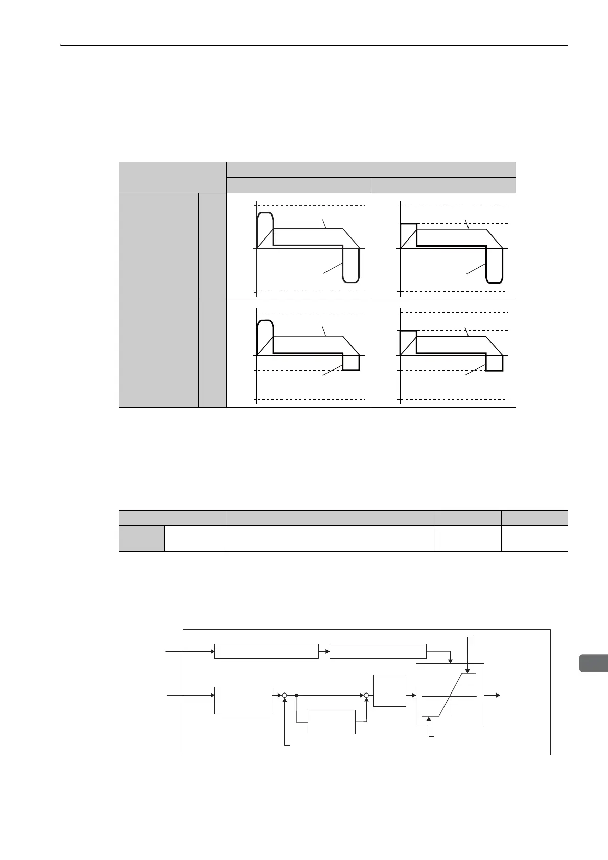
5.8.3 Torque Limiting Using an Analog Voltage Reference
For torque limiting by analog voltage reference, the torque is limited by using the analog voltage at the T-REF
terminals for CN1-9 and CN1-10.
From the torque limit value by analog reference and torque limit value by Pn402 and Pn403, whichever is
smaller will be applied.
This function can be used only during speed or position control, not during torque control.
The following chart shows when the torque limiting using an analog voltage reference is performed in the
speed control.
There is no polarity in the input voltage of the analog voltage reference for torque limiting. The absolute val-
ues of both + and - voltages are input, and a torque limit value corresponding to that absolute value is applied
in the forward and reverse direction.
/P-CL
OFF ON
/N-CL
OFF
ON
Pn402
Pn403
0
Torque
Speed
Pn403
0
Pn404
Pn402
Torque
Speed
0
Pn403
Pn405
Pn402
Torque
Speed
0
Pn403
Pn405
Pn404
Pn402
Torque
Speed
Parameter Meaning When Enabled Classification
Pn002 n.1
Uses the T-REF terminal as an external torque limit
input.
After restart Setup
Pn300
+
+
+
-
Pn400
T-REF
V-REF
T-REF filter time constant
Pn101
Pn415
Pn100
Torque reference input gain
Pn402
Speed
loop
gain
Speed feedback
Torque limit
value
Speed
reference
Torque
reference
Forward
torque limit
Pn403
Reverse torque limit
Multi-winding drive unit
Speed
reference input
gain
Speed loop
integral time
constant
(See 5.5.1.)
(See 5.3.1.)
(See 5.8.1.)
(See 5.8.1.)
(See 6.7.2.)

 Loading...


