6.1 Type of Adjustments and Basic Adjustment Procedure
6-5
6.1.3 Monitoring Operation during Adjustment
Check the operating status of the machine and signal waveform when adjusting the servo gain. Connect a mea-
suring instrument, such as a memory recorder, to an analog monitor connector on the multi-winding drive unit
to monitor the analog signal waveform.
The settings and parameters for monitoring analog signals are described in the following sections.
(1) Analog Monitor Connector Connections
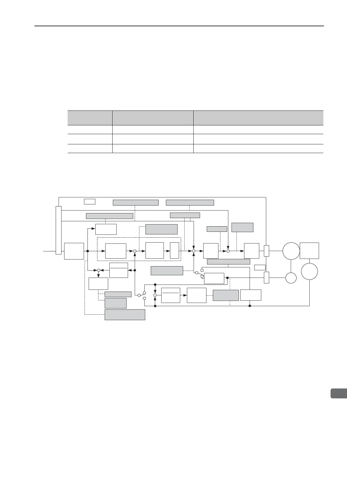
(2) Monitor Signal
The shaded parts in the following diagram indicate analog output signals that can be monitored.
Connector Pin
No.
Signal Name Factory Setting
CN1-16
Analog monitor 1 (TMON) Torque reference: 1 V/100% rated torque
CN1-17
Analog monitor 2 (VTG-M)
Motor speed: 1 V/1000 min
-1
CN1-1
Signal ground (SG) Analog monitor GND: 0 V
(U/V/W)
−
T-REF
V-REF
PULS
SIGN
1
Multi-winding drive system
Speed feedforward
Position reference speed
Position
amplifier error
Motor rotational
speed
Speed reference
Active gain
Tor qu e
reference
Speed
conversion
Electronic
gear
Speed
loop
Current
loop
Electronic
gear
1
Electronic
gear
Position loop
Torque feedforward
Error
counter
Error
counter
Error
counter
Load
MKp
Position error
Positioning
completed
Completion of position
reference
External encoder speed
Speed
conversion
Speed
conversion
Motor - load
position error
ENC
CN2
CN 1
External
ENC
*
*
Reference
Pulse
Multiplier
× n

 Loading...


