10 Appendix
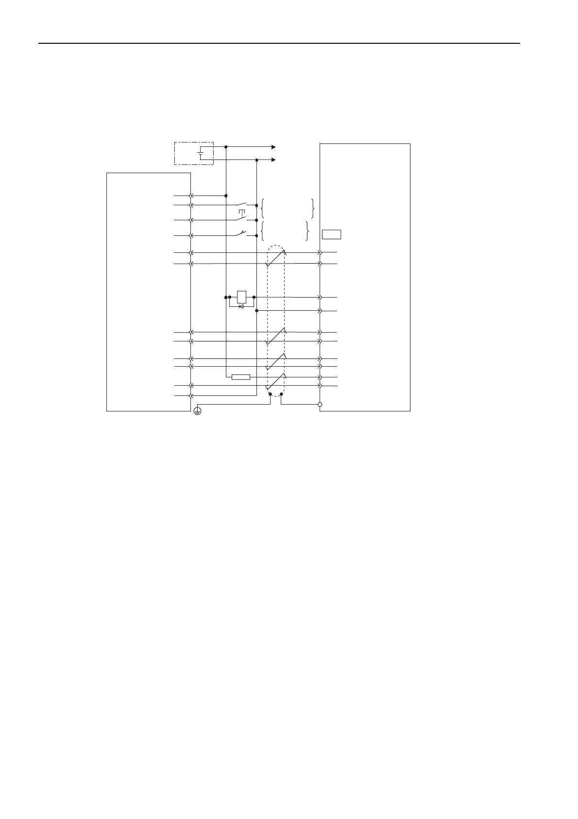
10.1.6 Connection to MITSUBISHI’s AD75 Positioning Module (Multi-Winding Drive Unit in Position Control)
10-8
10.1.6 Connection to MITSUBISHI’s AD75 Positioning Module
(Multi-Winding Drive Unit in Position Control)
∗
The ALM signal is output for about five seconds when the control power is turned ON. Take this into consideration
when designing the power ON sequence. Also, use the ALM signal to actuate the alarm detection relay 1Ry to stop the
main circuit power supply to the SERVOPACK and converter.
Note 1. Only the signals that are related to the multi-winding drive unit and Mitsubishi’s AD75 Positioning Module are
given in this example.
2. Incorrect signal connections may damage the Positioning Unit, multi-winding drive unit, SERVOPACKs, and
converters.
3. Open the signal lines not to be used.
4. The above connection diagram shows the connections for only one axis. When using other axes, make connec-
tions to the SERVOPACK in the same way.
5. Short-circuit the normally closed (NC) input terminals that are not used at the I/O connector section of the posi-
tioning module.
6. Make the settings so that the servomotor can be turned ON/OFF by the Servo ON (/S-ON) signal.
7. The SERVOPACK incorporates safety functions to protect people from the hazardous operation of the movable
parts of the machines, reduce the risk, and ensure the safety of the machine in operation. Necessary circuits and
settings are required in CN8 to use these functions. If these functions are not used, use the SERVOPACK with the
enclosed safety jumper connected to CN8. For details, refer to
5.11 Safety Function.
+
-
+24 V
0
24
V
1Ry
CN1
STOP
DOG
READY
PGO
PULSE
SIGN
CLEAR
1Ry
∗
2.2 KΩ
19
14
15
12
8
7
32
31
20
25
24
14
7
26
23
5
22
4
21
3
+24 V
PULS
CLR
SIGN
/PULS
/CLR
/SIGN
ALM+
ALM
-
PCO
/PCO
11
11
FG
I/O power
supply
X axis (Y axis)
ON when
positioning is
canceled
ON when
proximity is
detected
Positioning Module
AD75
manufactured by
Mitsubishi
Electric
Corporation
Connector shell
Multi-winding drive unit

 Loading...


