3.1 Main Circuit Wiring
3-9
Crimp Terminal Tools for SERVOPACKs and Converters
3.1.3 Typical Main Circuit Wiring Examples
Note the following points when designing the power ON sequence.
• Design the power ON sequence so that main power is turned OFF when a servo alarm signal (ALM) is output.
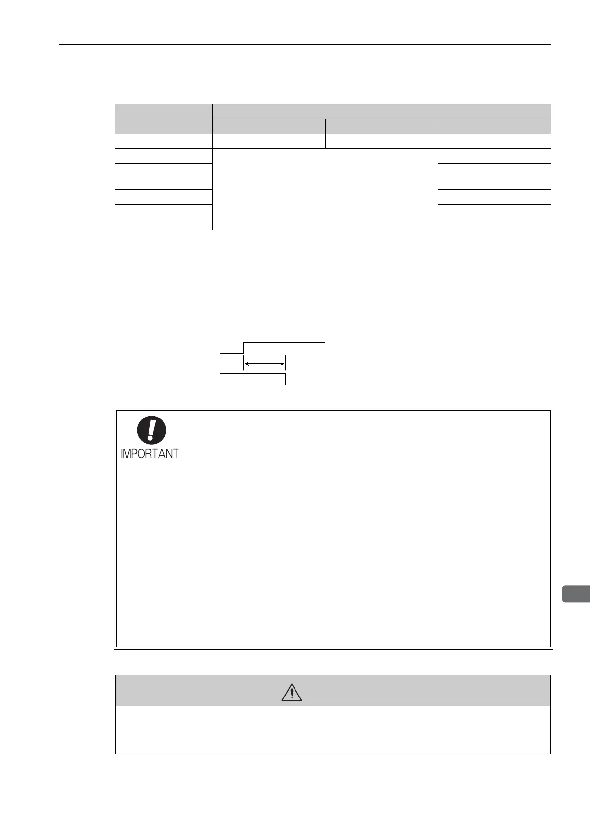
• The ALM signal is output (1Ry: OFF) for a maximum of five seconds when the control power is turned ON. Take this
into consideration when designing the power ON sequence and use this relay to turn OFF the main circuit power sup-
plies to the multi-winding drive unit, SERVOPACKs, and converters.
• Select the power supply specifications for the parts in accordance with the input power supply.
The typical main circuit wiring examples are shown below.
Model
Tools by J.S.T. Mfg Co., Ltd.
Body Head Dies
R5.5-6 YHT-2210 – –
R22-10
Body only: YPT-150-1
or
Body: YF-1; Head: YET-150-1
TD-223, TD-212
R38-8
R38-10
TD-224, TD-212
R60-8 TD-225, TD-213
70-8
70-10
TD-226, TD-213
Control power supply
ALM signal
5.0 s max.
• When you turn ON the control power supply and the main circuit power supply, turn
them ON at the same time or turn ON the main circuit power supply after the control
power supply.
When you turn OFF the power, first turn OFF the power for the main circuit and then
turn OFF the control power.
• Configure the system so that the control power supply to the multi-winding drive unit,
SERVOPACKs, and converters turns ON and OFF at the same time.
If the control power supply does not turned ON at the same time, the following alarms
will occur. If these alarms occur, turn the control power supply OFF and ON again.
• A.045: Multi-winding drive unit setting parameter error (Occurs in the multi-winding
drive unit.)
• A.CA0: Encoder parameter error (Occurs in the SERVOPACKs.)
• If the control power supply does not turned OFF at the same time, the following alarms
will occur.
These alarms, which occur when the power supply is turned OFF, do not require any
corrective action.
• A.EE6: Local communications disconnection error (Occurs in the multi-winding
drive unit.)
• A.E60: Local communications error (Occurs in the SERVOPACKs.)
WARNING
• High voltage may still remain in the SERVOPACKs and converters even after you turn OFF the main cir-
cuit power supplies. To prevent electric shock, do not touch the power supply terminals. When the voltage
is discharged, the charge indicator will turn OFF. Make sure the charge indicator is OFF before starting
wiring or inspections.

 Loading...


