10.1 Specifications for Communications with Connected Inverters
10-2
10.1 Specifications for Communications with Connected Inverters
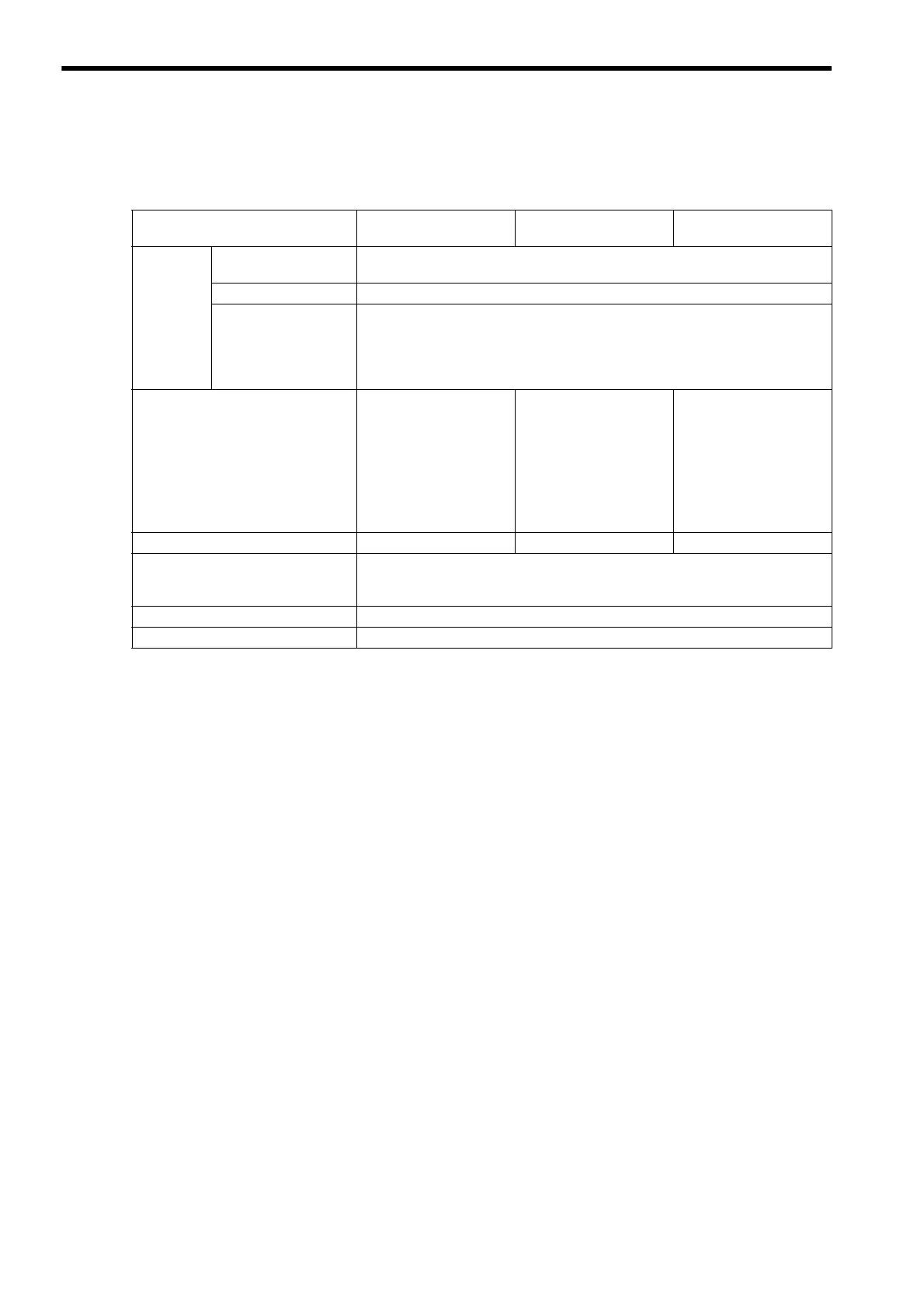
The following table provides the specifications required when connecting inverters through MECHATROLINK.
* 1. The maximum number of connectable inverters in MECHATROLINK-II 32-byte mode can be obtained by the fol-
lowing equation.
Transmission cycle 2 ms: 21 − C2 Message (with: 1, none: 0) − Number of retries to slaves
Transmission cycle 1 ms: 9 − C2 Message (with: 1, none: 0) − Number of retries to slaves
Setting range of number of retry to slaves is 0 to 7.
If the result of the above equation is 16 or greater, the maximum number of connectable inverters is 16.
* 2. The maximum number of connectable inverters in MECHATROLINK-II 17-byte mode can be obtained by the fol-
lowing equation.
Transmission cycle 1 ms: 15 − C2 Message (with: 1, none: 0) − Number of retries to slaves
Setting range of number of retries to slaves is 0 to 7.
Communication Specifications
MECHATROLINK-II
(32-byte)
MECHATROLINK-II
(17-byte)
MECHATROLINK-I
Supported
Models
SVB Module
Built-in SVB: With CPU version 2.20 or later
SVB-01: Version 1.10 or later
Engineering Tool
MPE720 version 5.12 or later
Inverter
VarispeedG7
VarispeedF7
VSminiV7
A1000
V1000
Number of Connectable Inverters
16 max.
(at transmission cycle 2
ms)
Differs depending on
whether or not the
message is used
and the number of
retries to slaves.
*1
15 max.
Differs depending on
whether or not the
message is used
and the number of
retries to slaves.
*2
14 max.
Transmission Cycle
1 ms or 2 ms 1 ms 2 ms
Interface
Fixed parameters (To set application conditions)
Setting parameters (To update references and output data)
Monitoring parameters (To update monitored or input data)
Self-configuration Function
Available
Others
Conforms with MECHATROLINK-I or -II specifications
 Loading...