10.4 Motion Parameter Details
10.4.2 Setting Parameter List
10-33
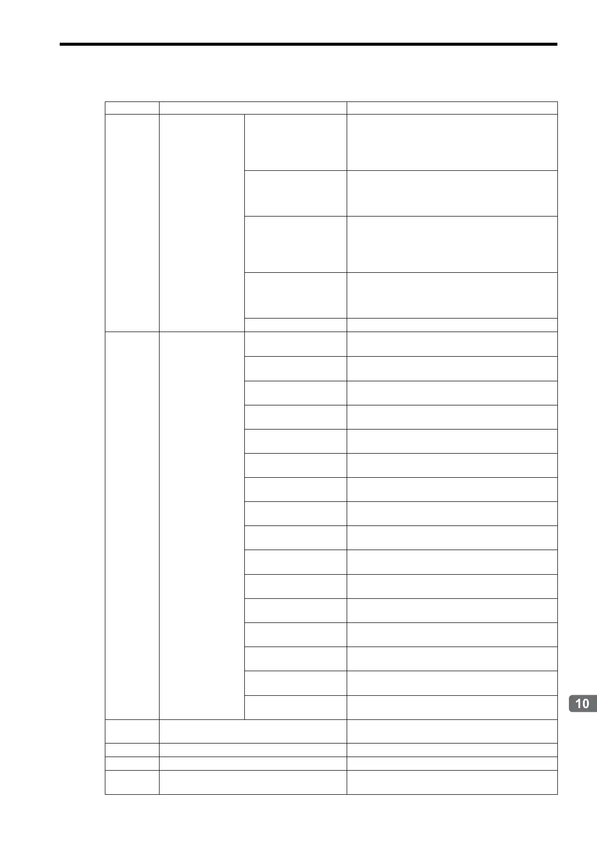
Settings for Connecting Inverters
OW0F
Auxiliary Input Data
Option Selection
(continued)
Bit 9: Multi-function
Analog Input A3
0: Disabled, 1: Enabled
When this bit is set to 1 (enabled), the output data option
Multi-function Analog Input A3 (IW1C) will be
monitored when the subcommand Inverter I/O Control is
executed.
Bit A: Multi-function
Input Terminal
0: Disabled, 1: Enabled
When this bit is set to 1 (enabled), the output data option
Digital Input Terminal (IW1D) will be monitored
when the subcommand Inverter I/O Control is executed.
Bit B: Multi-function
Analog Input A1
0: Disabled, 1: Enabled
When this bit is set to 1 (enabled), the output data option
Multi-function Analog Input A1 (IW1E) will be
monitored when the subcommand Inverter I/O Control is
executed.
Bit C: Encoder Counter
(ch2)
0: Disabled, 1: Enabled
When this bit is set to 1 (enabled), the output data option
Encoder Counter (ch2) (IW1F) will be monitored
when the subcommand Inverter I/O Control is executed.
Bits D to F
Reserved by the system
OW10
Input Command
Bit 0: Forward RUN
0: OFF, 1: ON
Forward run when ON
Bit 1: Reverse RUN
0: OFF, 1: ON
Reverse run when ON
Bit 2: Multi-function Input
Command S3
0: OFF, 1: ON (Initial value: External fault (EF3))
Bit 3: Multi-function
Input Command S4
0: OFF, 1: ON (Initial value: Error reset)
Bit 4: Multi-function
Input Command S5
0: OFF, 1: ON (Initial value: Multi-step reference 1)
Bit 5: Multi-function
Input Command S6
0: OFF, 1: ON (Initial value: Multi-step reference 2)
Bit 6: Multi-function
Input Command S7
0: OFF, 1: ON (Initial value: JOG command)
Bit 7: Multi-function
Input Command S8
0: OFF, 1: ON (Initial value: External baseblock)
Bit 8: External Fault Input
(EFO)
0: OFF, 1: ON
Bit 9: Fault Reset
0: OFF, 1: ON
Clears alarm or warning in the Inverter when ON
Bit A: Multi-function
Input Command S9
0: OFF, 1: ON (Initial value: Multi-step reference 3)
Bit B: Multi-function
Input Command S10
0: OFF, 1: ON (Initial value: Multi-step reference 4)
Bit C: Multi-function
Input Command S11
0: OFF, 1: ON (Initial value: Acceleration/deceleration
time switch 1)
Bit D: Multi-function
Input Command S12
0: OFF, 1: ON (Initial value: Emergency stop)
Bit E: Fault Trace Clear
0: OFF, 1: ON
Clears error history trace when ON.
Bit F: External Base
Block Command
0: OFF, 1: ON
OW11
Freq
uency Reference
Units: According to
n035 for VSminiV7, and o1-03 for
Varispeed G7 and F7
OW12
Torque Reference
Units: 0.1%
OW13
Torque Compensation (Option)
Units: 0.1%
OW14
Multi-function Analog Output FM
(Option)
Units: -1540 to +1540/-11 V to +11 V (Varispeed G7 and
F7)
(cont’d)
Register No. Name Contents

 Loading...


