Appendix I Servo Driver Transmission Reference Mode
I.3 Motion Parameters That Can be Used in Servo Driver Transmission Reference Mode
A-40
I.3 Motion Parameters That Can be Used in Servo Driver Transmission Reference
Mode
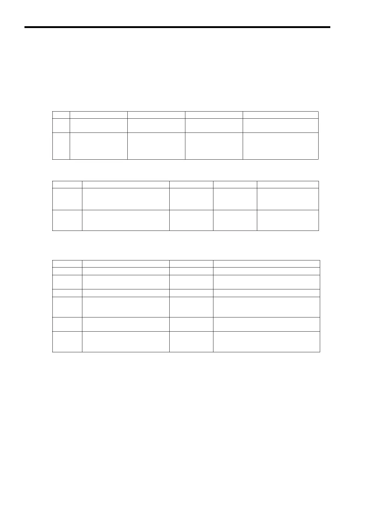
The motion parameters that can be used in transparent command mode are limited to those listed below. Motion Com-
mands other than those listed below cannot be used.
Motion Fixed Parameters
Motion Setting Parameters
* For SVB-01 Module version 1.20 or later or built-in SVB Module version 2.50 or later
Motion Monitoring Parameters
I.4 MECHATROLINK Commands That Cannot Be Used
Do not use the following MECHATROLINK commands unless it is absolutely necessary, since connection manage-
ment is carried out by the system.
• Connection request command (CONNECT)
• Disconnection request command (DISCONNECT)
• Synchronization request command (SYNC_SET)
• Device setup request command (CONFIG)
• Sensor ON command (SENS_ON)
• Sensor OFF command (SENS_OFF)
No. Name Setting Range Default Setting Description
1
Function Selection
Flag 1
Bit setting 0
Bit 8: Interpolation Segment dis-
tribution Processing
2
Function Selection
Flag 2
Bit setting 0
Bit 0: Communication Abnor-
mality Detection Mask
Bit 1: WDT Abnormality
Detection Mask
Register Name Setting Range Default Setting Description
OW00 Run Command Setting
Bit setting 0
Bit E: Communication
Reset
*
Bit F: Clear Alarm
0W70
to
OW7E
Command Buffer for Servo Driver
Transmission Reference Mode
0
Register Name Setting Range Description
IW00 RUN Status
Bit setting Bit 0: Motion Controller Operation Ready
IW01
Parameter Number When Range
Over is Generated
0 to 65535
IL02 Warning
Bit setting Bit 2: Fixed Parameter Error
IL04 Alarm
Bit setting
Bit 10: Servo Driver Synchronization
Communication Error
Bit 11: Servo Driver Communication Error
IL18
Machine Coordinate System Latch
Position (LPOS)
-2
31
to 2
31
-1
IW70
to
IW7E
Response Buffer for Servo Driver
Transmission Reference Mode

 Loading...


