11.1 Controlling Vertical Axes
11.1.3 Connections to Σ-I Series SGDB SERVOPACK
11-6
11.1.3 Connections to Σ-I Series SGDB SERVOPACK
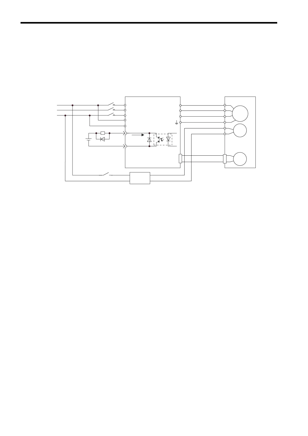
( 1 ) Example of a Brake ON and OFF Circuit
A circuit is configured to turn the brake ON and OFF using the /BK contact output signal from the SERVOPACK and a
brake power supply. The following diagram shows the standard connections.
* 1. The terminal is allocated using parameter Cn-2D. In the example above, /BK signal 4 is set in the
2nd digit.
* 2. Brake control relay contact
* 3. There are 200-V and 100-V brake power supplies.
Power supply
M
BK
PG
U
V
W
CN2
Red
Black
White
AC DC
BK-RY
+24 V
R
S
T
r
t
Brake power supply
SGDB SERVOPACK
27
28
A
B
C
D
E
F
/BK
SG-COM
*
2
*
3
BK-RY
*
1
*
1
50 mA
max.
Blue or
yellow
Servomotor
with a brake
 Loading...