Programming 5 - 20
In order to use parameter b5-19 as the PI Setpoint, set parameter b5-18= “1: Enabled”. If b5-18= “0: Disabled” the PI Set-
point will either be:
• Modbus Register 06H (If Register 0FH bit 1 is high)
• The active speed command (i.e. Determined by the setting of b1-01). See Table 1 “Setpoint Options”
" b5-19 PI Setpoint Value
Setting Range: 0.00 to 100.00%
Factory Default: 0.00%
Parameter b5-19 is for a PI Setpoint value. When b5-18= “1: Enabled”, the value of b5-19 will take precedent over any other
PI setpoint unless the Drive is set up for Differential Feedback, in which case, b5-18 and b5-19 have no affect on the PI
function.
" b5-20 PI Setpoint Display Scaling
The PI Setpoint Display Scaling value (b5-20) is a scaling factor that is applied to the monitor display for both the PI Setpoint
(U1-38) and the PI Feedback (U1-24).
If the monitors seem more natural in terms of percentage, set b5-20= 1. If the monitors are easier to work with when
displaying the equivalent synchronous RPM, set b5-20= [the number of motor poles].
If another engineered unit, such a fpm or cfm, is desired, set b5-20= xxxxx where
X X X X X
Digit 5 Digit 4 Digit 3 Digit 2 Digit 1
Digits 1 through 4 set the desired number to be displayed at 100% speed.
Digit 5 determines the number of decimal places
If Digit 5 = 0 number format is XXXX
If Digit 5 = 1 number format is XXX.X
If Digit 5 = 2 number format is XX.XX
If Digit 5 = 3 number format is X.XXX
Setting Description
0Hz (factory default)
1%
3 RPM (Synchronous)
3 Engineering Units
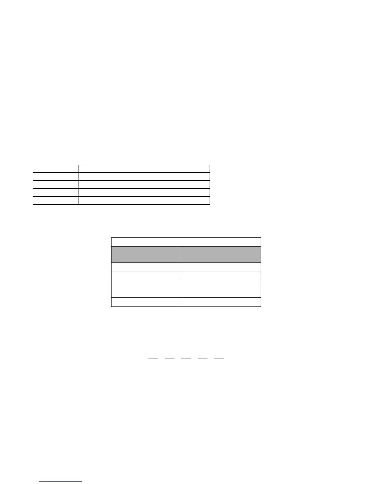
Table 2 PI Setpoint Display Scaling Options
If b5-20 is:
U1-24 and U1-38
Display Increments.
00.01 Hz
10.00%
2 through 39
(enter the # of motor poles)
0 R P M
40 through 39999 Engineering Units