Programming 5 - 35
" H3-08 Terminal A2 Signal Level
The H3-08 parameter (Terminal A2 Signal Level) allows the programmer to specify the signal that will be applied to the A2
analog input. The A2 analog input can accept either a 0–10 Vdc or 4-20 mA signal as a reference. The Drive also has a
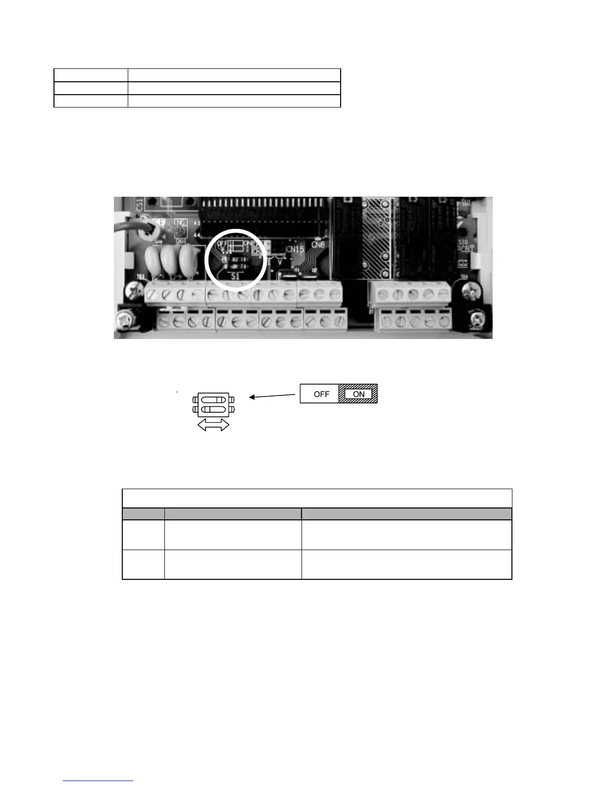
DIP switch (S1) on the removable terminal board that must be set for the proper reference signal into the A2 analog input. The
S1-2 dipswitch setting determines the internal resistance of the A2 input while parameter H3-08 determines how the Drive
interprets the measured signal.
Fig. 27 DIP Switch S1
Setting Description
0 0 - 10VDC
2 4 - 20mA (Default)
Table 4 DIP Switch S1
Name Function Setting
S1-1
RS-485 and RS-422 terminating
resistance
OFF: No terminating resistance
ON: Terminating resistance of 110 Ω
S1-2 Input signal for analog input A2
OFF: 0 to 10 V (internal resistance: 20 kΩ)
ON: 4 to 20 mA (internal resistance: 250 Ω) (Default)
S1
1
Terminating
resistance
DIP Switch S1-1 located on
terminal board.
2
1