Programming 5 - 34
Fig. 24 Output Frequency as Commanded via Analog Input with Increased Gain Setting
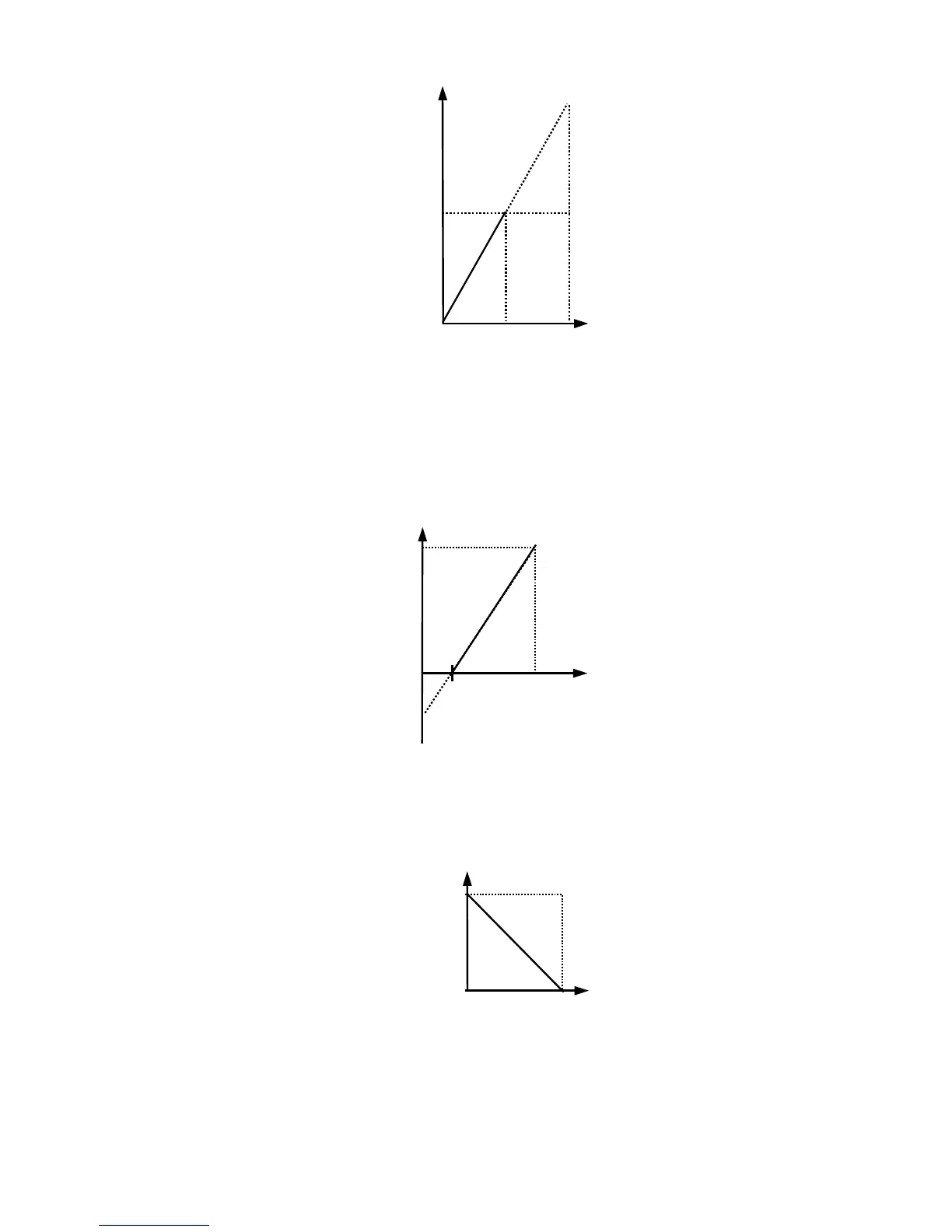
Adjustment of the bias setting will likewise adjust the speed command that is equivalent to the minimum analog input level
(0Vdc or 4mA). If, for instance, the bias is set to –25%, then 0Vdc or 4mA will be equivalent to a –25% speed command.
Since the minimum speed command is 0% an analog input of 2.5 to10Vdc or 8 to 20mA will now be equivalent to 0-100%
speed command span.
Fig. 25 Output Frequency with Reduced Bias Setting
As a further example, for an inverse-acting speed command, set the bias= 100% and the gain= 0%. The minimum analog input
level (0Vdc or 4mA) will produce a 100% speed command and the maximum analog input level (10Vdc or 20mA) will pro-
duce a 0% speed command.
Fig. 26 Output Frequency with Inverted Gain and Bias Settings
4mA
20mA
0V
10V
Bias = 0%
Output
Frequency
Analo
In
ut Level
Gain =200%
100%
Analog Input Signal
5V
12mA
0V
4mA
10V
20mA
Gain = 100%
Bias = -25%
Output
Frequency
Analog Input Level
2.5V
8mA
Analog Input Signal
20mA
4mA
0V
10V
Gain = 100%
Bias = 0%
Output
Frequency
Analog Input Level
Analog Input Signal
Bias
Gain