Electrical Installation 2 - 2
Terminal Block Configuration
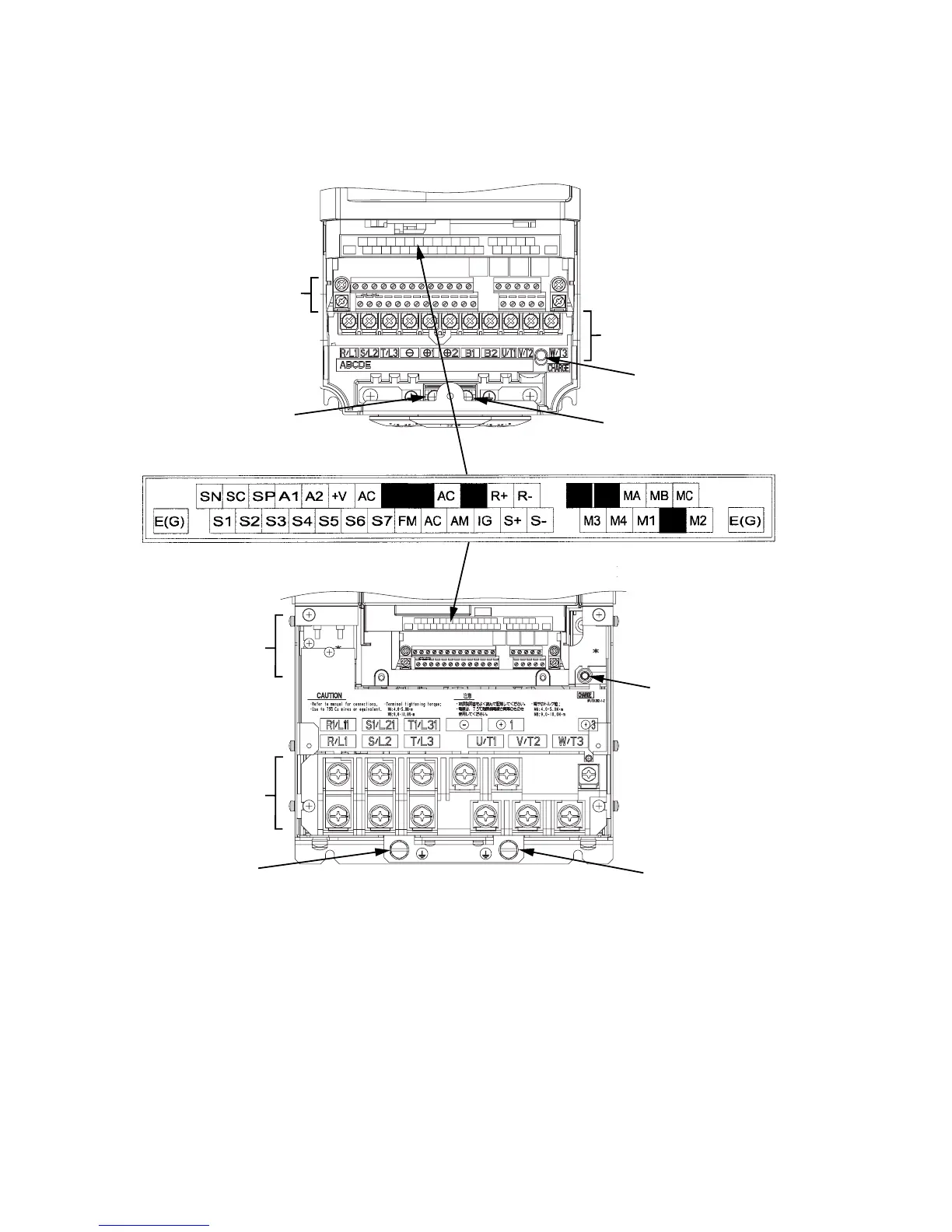
The wiring terminals are shown in Fig 2.1.
Fig 2.1 Control Circuit Terminal Layout
Models CIMR-_ _ _2018 (25 HP, 208V)/
4018 (30 HP, 480V) and smaller
Models CIMR-_ _ _2022 (30 HP, 208V)/
4030 (40 HP, 480V) and larger
AC MP
AMS6
-V
IG
R- M5
FM
R+RP
S1
S4
SP
S7 M4
+V
S3
SC
S+
A2
M2
SN M6
AC
A1
E(G) E(G)
MCMB
S5
M1
AC MA
M3S2 S-
AC MP
AMS6
-V
IG
R- M5
FM
R+RP
S1
S4
SP
S7 M4
+V
S3
SC
S+
A2
M2
SN M6
AC
A1
E(G)
E(G)
MCMB
S5
M1
AC MA
M3S2 S-
Ground terminal
Ground terminal
Ground terminal
Ground terminal
Charge indicator
Charge indicator
Main circuit terminals
Main circuit terminals
Control circuit terminals
Control circuit terminals