Capacity Related Parameters B - 4
Capacity Related Parameter Values
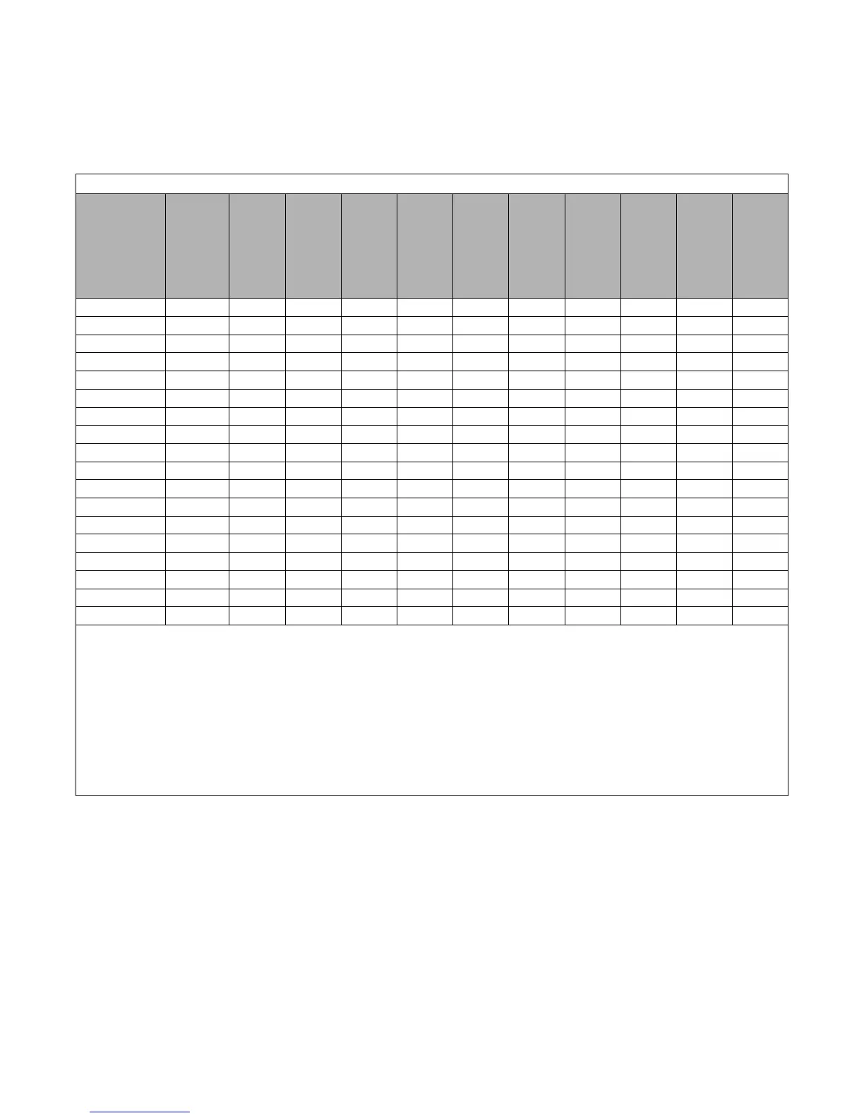
The following tables detail the factory default settings for the parameters that are affected by the setting of parameter o2-04.
Table B.3 208/240VAC Drives
Drive Model
CIMR-P7U
Nominal
Hp
Factory
Default
for
b8-04
Factory
Default
for
C6-02
and
C6-03
Factory
Default
for
E2-01
Factory
Default
for
E2-03
Factory
Default
for
E2-05
Factory
Default
for
L2-02
Factory
Default
for
L2-03
Factory
Default
for
L2-04
Factory
Default
for
L8-02
Factory
Default
for
L8-06
20P4
0.5/0.75
288.2 10kHz 1.9 1.2
9.842 0.1 0.1 0.3 95° C5
20P7 2
223.7 10kHz
3.3 1.8 5.156 0.1 0.2 0.3 95° C7.5
21P5 1.5/2
169.4 10kHz
6.2 2.8 1.997 0.2 0.3 0.3 95° C10
22P2 3
156.8 8kHz
8.5 3.0 1.601 0.3 0.4 0.3 100 ° C12
23P7 5
122.9 10kHz
14.0 4.5 0.771 0.5 0.5 0.3 95° C12
25P5 7.5
94.75 15kHz
19.6 5.1 0.399 1.0 0.6 0.3 95° C10
27P5 10
72.69 15kHz
26.6 8.0 0.288 1.0 0.7 0.3 95° C17
2011 15
70.44 8kHz
39.7 11.2 0.230 1.0 0.8 0.3 95° C21
2015 20
63.13 10kHz
53.0 15.2 0.138 2.0 0.9 0.3 90° C17
2018 25 57.87 10kHz
65.8 15.7 0.101 2.0 1.0 0.6 100° C15
2022 30
51.79 10kHz
77.2 18.5 0.079 2.0 1.0 0.6 90° C24
2030 40
46.27 10kHz
105.0 21.9 0.064 2.0 1.1 0.6 90° C20
2037 50
38.16 5kHz
131.0 38.2 0.039 2.0 1.1 0.6 95° C18
2045 60
35.78 5kHz
160.0 44.0 0.030 2.0 1.2 0.6 100° C20
2055 75
31.35 8kHz
190.0 45.6 0.022 2.0 1.2 0.1 105° C17
2075 75/100
23.10 2kHz
260.0 72.0 0.023 2.0 1.3 0.1 110° C16
2090 125
20.65 2kHz
260.0 72.0 0.023 2.0 1.5 0.1 100° C18
2110 150
18.12 2kHz
260.0 72.0 0.023 2.0 1.7 0.1 95° C20
Note: b8-04 = Energy Savings Coefficiant
C6-02 = Carrier Frequency
C6-03 = Carrier Frequency Upper Limit
E2-01 = Motor Rated Current
E2-03 = Motor No-Load Current
E2-05 = Motor Line-to-Line Resistance
L2-02 = Momentary Power Loss Ride-Thru Time
L2-03 = Momentary Power Loss Minimun Base Block Time
L2-04 = Momentary Power Loss Voltage Recovery Ramp Time
L8-02 = Overheat Pre-Alarm Level
L8-06 = Input Phase Loss Detection Level