Electrical Installation 2 - 23
! Control Circuit Terminal Functions
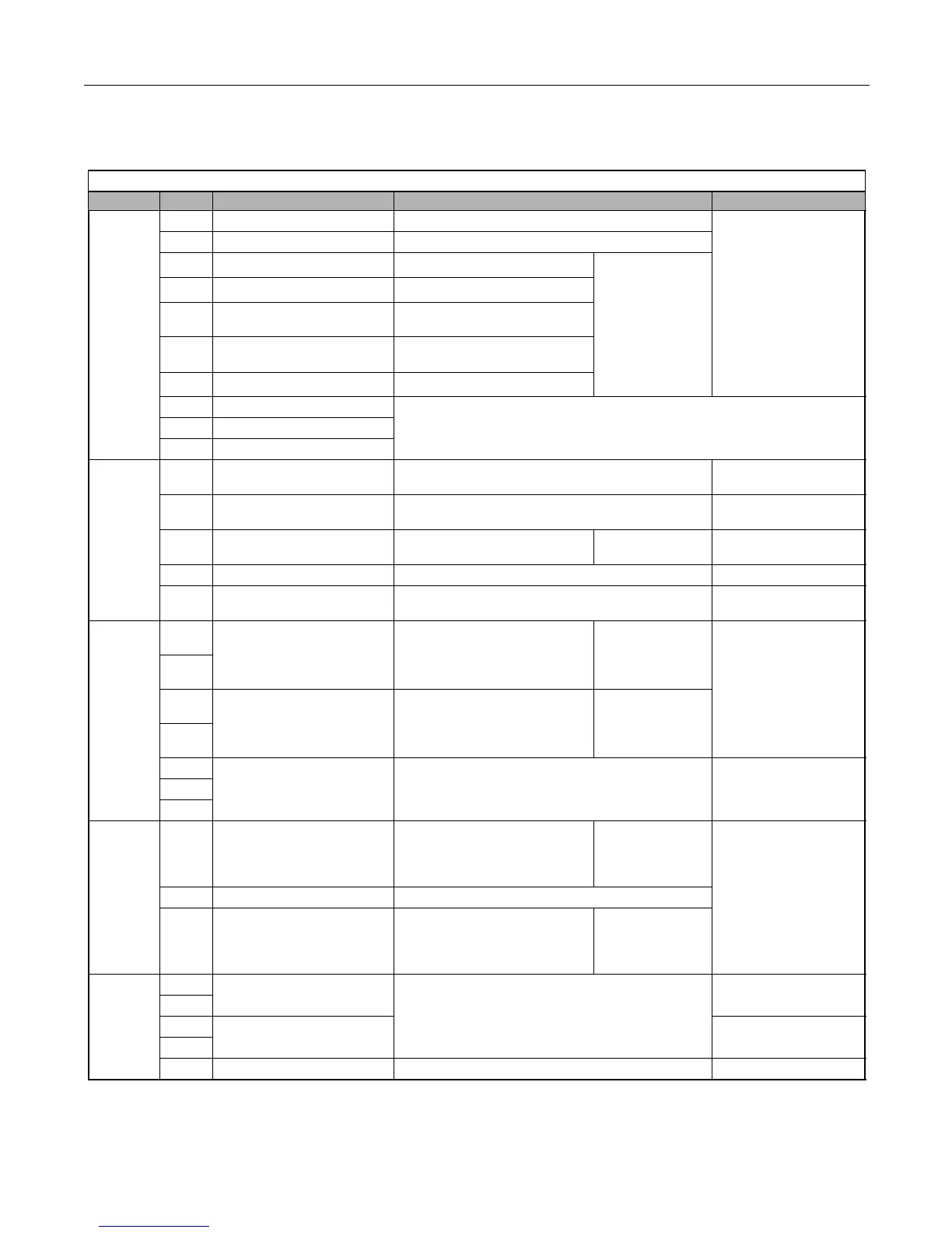
The factory default functions of the control circuit terminals for 2-wire control are shown in Table below.
Table 2.11 Control Circuit Terminals
Type No. Signal Name Description Signal Level
Digital
input
signals
S1 Forward run/stop command Forward run when CLOSED; stopped when OPEN.
24 Vdc, 8 mA
Photocoupler isolation
S2 Reverse run/stop command Reverse run when CLOSED; stopped when OPEN.
S3
External fault input
Fault when CLOSED.
Multi-function
digital inputs
Functions set by
H1-01 to H1-05.
S4
Fault reset
Reset when CLOSED
S5
Multi-step speed reference 1
(Master/auxiliary switch)
Auxiliary frequency reference
when CLOSED.
S6
Multi-step speed reference 2
Multi-step setting 2 when
CLOSED.
S7
Jog frequency reference
Jog frequency when CLOSED.
SN Digital input supply common
Refer to Table 2.14 for connection details.
SC Digital input photocoupler
SP Digital input supply +24Vdc
Analog
input
signals
+V +15Vdc power output +15Vdc power supply for analog inputs or transmitters
+15Vdc
(Max. current: 20 mA)
A1
Analog input or
Speed Command
0 to +10Vdc/100% 0 to +10 V(20 kΩ)
A2 Multi-function analog input
4 to 20 mA/100%
0 to +10Vdc/100% (H3-0
Function set by
H3-09.
4 to 20 mA(250Ω)
0 to +10 V(20kΩ)
AC Analog common – –
E(G)
Shield wire, optional ground
line connection point
––
Digital
output
signals
M1
During Run
(N.O. contact)
CLOSED during operation
Multi-function
digital output
Function set by
H2-01.
Dry contacts
Contact capacity:
1 A max. at 250Vac
1 A max. at 30Vdc
M2
M3
Remote/Auto Operation
(N.O. contact)
CLOSED when local control
Multi-function
digital output
Function set by
H2-02.
M4
MA
Fault output signal
(SPDT)
MA/MC: CLOSED during fault condition
MB/MC: OPEN during fault condition
Dry contacts
Contact capacity:
1 A max. at 250Vac
1 A max. at 30Vdc
MB
MC
Analog
output
signals
FM Multi-function analog output
(output frequency)
0 to +10Vdc/100% frequency
Multi-function
analog monitor 1
Function set by
H4-01
0 to +10Vdc max. ±5%
2 mA max.
AC Analog common –
AM Multi-function analog output
(output current)
0 to +10Vdc/100% Drive's rated
output current
Multi-function
analog monitor 2
Function set by
H4-04
RS-485/
422
R+
Modbus
communication input
For 2-wire RS-485, jumper R+ and S+ and
jumper R- and S-.
Differential input,
PHC isolation
R-
S+
Modbus
communication output
Differential input,
PHC isolation
S-
IG Signal common - -