Electrical Installation 2 - 21
Control Wiring
! Control Circuit Wire Sizes
The auto mode speed reference (speed command) field wiring connection is made to P7 Drive terminals A1 or A2 (signal
positive), AC (signal common) and G (shield). Keep this lead length as short as possible to maintain signal quality. Insulated
twisted shielded pair wire (2 conductor # 18 ga, Belden 8760 or equivalent) is required. Do not run these wires in the same
conduits as other AC power or control wires. The shield must be connected on this end only, stub and isolate the other end.
The A2 signal employed is 4 to 20 mA with parameter H3-08 set for “2: 4 - 20 mA”. For 0 to 10 VDC, parameter H3-08 is set
for “0: 0 - 10 VDC” and the P7 control board DIP switch S1-2 must be in the OFF position. (See Figure 2.9)
For remote operation, keep the length of the control wiring to 50m or less. Separate the control wiring from high-power lines
(input power, motor leads or relay sequence circuits) to reduce noise induction from peripheral devices.
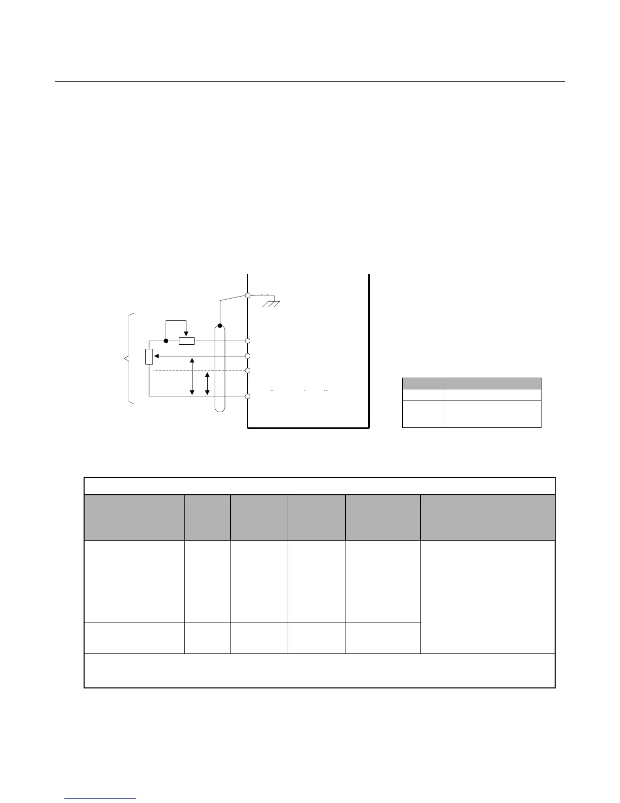
When setting speed commands (frequency references) from an external speed potentiometer (and not from the Digital Opera-
tor), use shielded twisted-pair wires and ground the shield to terminal E(G), as shown in Fig 2.9. Terminal numbers and wire
sizes are shown in Table 2.10.
Fig 2.9 Analog Input Terminal Configuration
Table 2.10 Terminal Numbers and Wire Sizes (Same for all Drives)
Terminals
Ter mi nal
Screws
Tightening
Tor qu e
lb-in
(N•m)
Possible
Wire Sizes
AWG (mm
2
)
Recommended
Wire Size AWG
(mm
2
)
Wire Type
S1, S2, S3, S4, S5, S6, S7
SN, SC, SP, +V, A1, A2,
AC, MI, M2, M3, M4,
MA, MB, MC, FM, AC,
AM, R+, R-, S+, S-, IG
Phoenix
type
*3
4.2 to 5.3
(0.5 to 0.6)
Stranded
wire:
26 to 16
(0.14 to 1.5)
18
(0.75)
• Shielded, twisted-pair wire
*1
• Shielded, polyethylene-covered,
vinyl sheath cable
E(G) M3.5
7.0 to 8.8
(0.8 to 1.0)
20 to 14
(0.5 to 2
*2
)
12
(1.25)
*1.Use shielded twisted-pair cables to input an external speed command.
*2.Yaskawa recommends using straight solderless terminals on digital inputs to simplify wiring and improve reliability.
*3. Yaskawa recommends using a thin-slot screwdriver with a 3.5 mm blade width.
Signal Terminal Connections
0-10Vdc A1 to AC
4-20mA
or
0-10Vdc
A2 to AC
(P=Pair)
E(G)
+V +15VDC, 20mA
A1 0- 10VDC (20K )
A2 H3- 08
4- 20mA (250K )
[0 to +10V (20K )]
AC
E7
Ω
Ω
Ω
4 t o 20mA
PP
Ext ernal
Frequency
Ref er enc e
2k
Ω
2k
External
Frequency
Reference
E (G)
2kΩ
2k
P P
4 to 20m A
+V +15VDC, 20mA
A1 0-10VDC (20k Ω)
A2 H3-08
4-20m A (250K Ω)
[0 to +10V (20K Ω)]
AC