Parameters A - 5
Speed Search
b3-01
Speed Search Selection
SpdSrch at Start
Enables/disables and selects the speed search function at start.
0: SpdsrchF Disable - Speed search at start is disabled
(estimated speed method is used at other times)
1: SpdsrchF Enable - Speed search is enabled
(estimated speed method)
2: SpdsrchI Disable - Speed search at start is disabled
(current detection method is used at other times)
3: SpdscrhI Enable - Speed search is enabled
(current detection method)
Estimated Speed Method:
Actual motor speed and direction is estimated, then the motor is
ramped from that speed to the commanded speed.
Current Detection Method:
Current level is monitored while output frequency is ramped down.
0 to 3 2 Programming
b3-02
Speed Search Deactivation
Current
SpdSrch Current
Used only when b3-01 = 3. Sets the speed search operation current
as a percentage of drive rated current.
0 to 200 120% Programming
b3-03
Speed Search Deceleration
Time
SpdSrch Dec Time
Used only when b3-01 = 3. Sets the deceleration time during speed
search.
0.1 to 10.0 2.0sec Programming
b3-05
Speed Search Delay Time
Search Delay
Delays the speed search operation after a momentary power loss to
allow time for an external output contactor to re-energize.
0.0 to
20.0sec
0.2sec Programming
b3-14
Bidirectional Speed Search
Selection
Bidir Search Sel
0: Disabled
1: Enabled
0 or 1 1 Programming
Delay Timers
b4-01
Timer Function ON-Delay
Time
Delay-ON Timer
Used in conjunction with a multi-function digital input and a multi-
function digital output. This sets the amount of time between when
the digital input is closed, and the digital output is energized.
0.0 to
3000.0
0.0sec Programming
b4-02
Timer Function OFF-Delay
Time
Delay-OFF Timer
Used in conjunction with a multi-function digital input and a multi-
function digital output. This sets the amount of time the output
stays energized after the digital input is opened.
0.0 to
3000.0
0.0sec
Programming
PI Control
b5-01
PI Mode Setting
PI Mode
This parameter enables / disables the closed loop (PI) controller.
0: Disabled
1: Enabled (commanded speed becomes PI setpoint)
3: Fref+PI
0, 1, 3 0 Quick Setting
b5-02
!
Proportional Gain Setting
P Gain
Sets the proportional gain of the PI controller.
0.00 to
25.00
2.00 Quick Setting
b5-03
!
Integral Time Setting
PI I Time
Sets the integral time for the PI controller. A setting of zero dis-
ables integral control.
0.0 to 360.0 5.0sec Quick Setting
b5-04
!
Integral Limit Setting
PI I Limit
Sets the maximum output possible from the integrator. Set as a %
of fmax.
0.0 to
100.0
100% Quick Setting
b5-06
!
PI Output Limit
PI Limit
Sets the maximum output possible from the entire PI controller.
Set as a % of fmax.
0.00 to
100.0
100.0% Quick Setting
b5-07
!
PI Offset Adjustment
PI Offset
Sets the amount of offset of the output of the PI controller. Set as a
% of fmax.
The PI Offset Adjustment parameter has two different uses. Param-
eter b5-07 serves different functions depending on whether it is
used on a standard PI loop or a Differential PI loop.
1: Parameter b5-07 causes an offset to be applied to the output of
the PI function in a non-Differential PI loop. Every time the PI
output is updated, the offset is summed with the PI output. This
can be used to artificially kick-start a slow starting PI loop.
2: If the Drive is configured for Differential PI Regulation
(H3-09=16), then the PI Offset is the targeted maintained differ-
ential between the signal measured on analog input A1 and the
signal measured on analog input A2.
–100.0 to
+100.0
0.0% Quick Setting
b5-08
!
PI Primary Delay Time
Constant
PI Delay Time
Sets the amount of time for a filter on the output of the PI
controller.
0.00 to
10.00
0.00sec Quick Setting
b5-09
PI Output Level Selection
Output Level Sel
Determines whether the PI controller will be direct or reverse
acting.
0: Normal Output (direct acting)
1: Reverse Output (reverse acting)
0 or 1 0 Quick Setting
!Denotes that parameter can be changed when the drive is running.
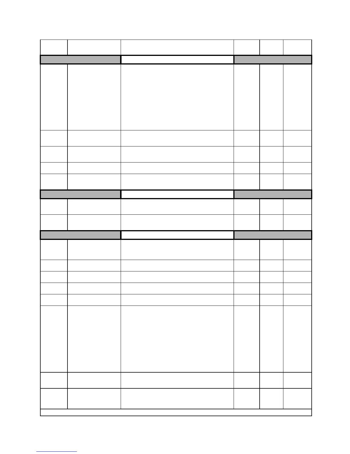
Table 1: Parameter List (Continued)
Parameter
No.
Parameter Name
Digital Operator Display
Description
Setting
Range
Factory
Setting
Menu
Location