Communications D - 10
Monitor Data
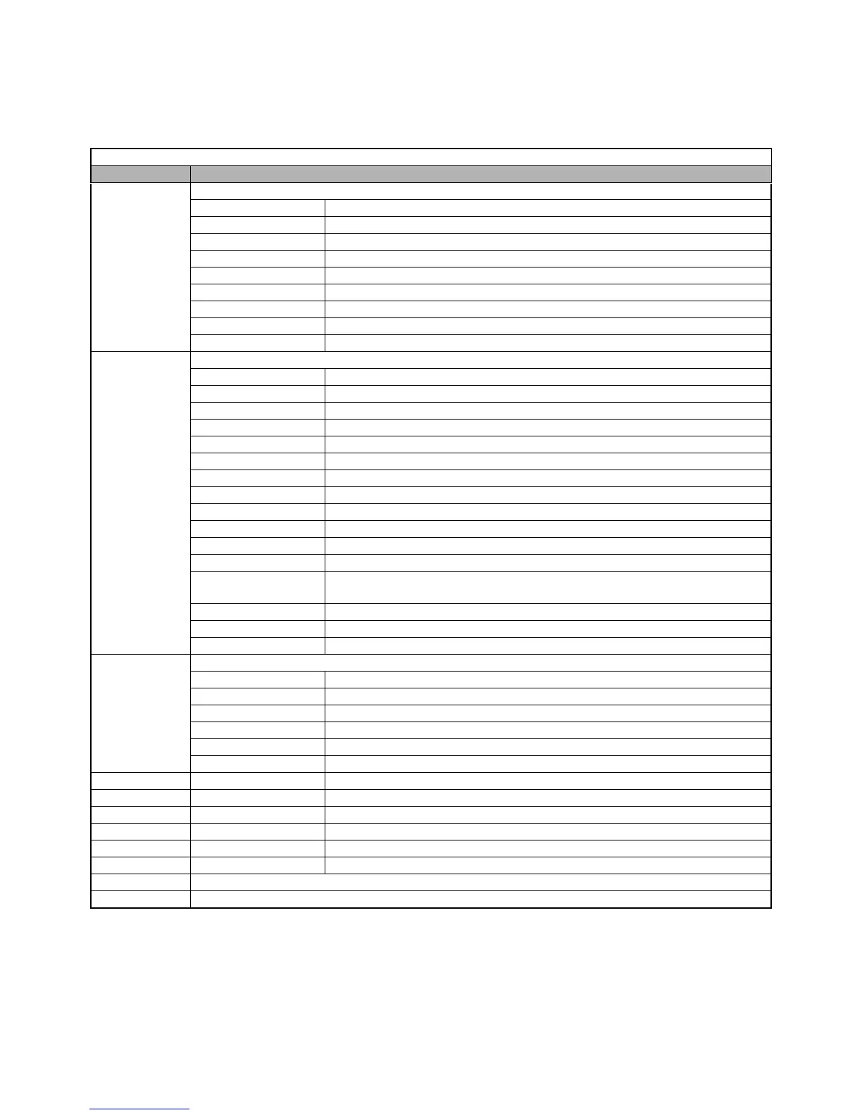
The following table shows the monitor data. Monitor data can only be read.
Table D.5 Monitor Data
Register No. Contents
0020H
Drive status
Bit 0 Operation 1: Operating 0: Stopped
Bit 1 Reverse operation 1: Reverse operation 0: Forward operation
Bit 2 Drive startup complete 1: Completed 0: Not completed
Bit 3 Fault 1: Fault
Bit 4 Data setting error 1: Error
Bit 5 Multi-function digital output 1 (terminal M1 - M2) 1: ON 0: OFF
Bit 6 Multi-function digital output 2 (terminal M3 - M4) 1: ON 0: OFF
Bit 7 Not used
Bits 8 to F Not used
0021H
Fault details
Bit 0 Overcurrent (OC) Ground fault (GF)
Bit 1 Main circuit overvoltage (OV)
Bit 2 Drive overload (OL2)
Bit 3 Drive overheat (OH1, OH2)
Bit 4 Not used
Bit 5 Fuse blown (PUF)
Bit 6 PI feedback reference lost (FbL)
Bit 7 External error (EF, EFO)
Bit 8 Hardware error (CPF)
Bit 9 Motor overload (OL1) or overtorque 1 (OL3) detected
Bit A PG broken wire detected (PGO), Overspeed (OS), Speed deviation (DEV)
Bit B Main circuit undervoltage (UV) detected
Bit C
Main circuit undervoltage (UV1), control power supply error (UV2), inrush prevention
circuit error (UV3), power loss
Bit D Missing output phase (LF)
Bit E Modbus communications error (CE)
Bit F Operator disconnected (OPR)
0022H
Data link status
Bit 0 Writing data
Bit 1 Not used
Bit 2 Not used
Bit 3 Upper and lower limit errors
Bit 4 Data integrity error
Bits 5 to F Not used
0023H Frequency reference U1-01
0024H Output frequency U1-02
0025H Output voltage reference U1-06
0026H Output current U1-03
0027H Output power U1-08
0028H Torque reference U1-09
0029H Not used
002AH Not used