Electrical Installation 2 - 7
4185 300/350
R/L1, S/L2, T/L3, , 1
M8
88.5
(10.0)
300 X 2P
(152 X 2P)
600Vac
UL Approved
vinyl-sheathed
or equivalent
U/T1, V/T2, W/T3, R1/L11, S1/L21, T1/L33 M8
88.5
(10.0)
300 X 2P
(152 X 2P)
3
M8
88.5
(10.0)
2/0
(67.4)
M16
867.4
(98.0)
3/0 X 2P
(85 X 2P)
r/
l1, s200/l
2
200, s400/l
2
400 M4
12.4
(1.4)
14
(2.1)
4220 400/450
R/L1, S/L2, T/L3, , 1
M8
88.5
(10.0)
500 X 2P
(253 X 2P)
U/T1, V/T2, W/T3, R1/L11, S1/L21, T1/L33 M8
88.5
(10.0)
400 X 2P
(203 X 2P)
3
M8
88.5
(10.0)
2/0
(67.4)
M16
867.4
(98.0)
250 X 2P
(127 X 2P)
r/
l1, s200/l
2
200, s400/l
2
400 M4
12.4
(1.4)
14
(2.1)
4300 500+
R/L1, S/L2, T/L3, , 1
M8
88.5
(10.0)
700 X 2P
(355 X 2P)
U/T1, V/T2, W/T3, R1/L11, S1/L21, T1/L33 M8
88.5
(10.0)
600 X 2P
(304 X 2P)
3
M8
88.5
(10.0)
2/0
(67.4)
M8
867.4
(98.0)
400 X 2P
(203 X 2P)
r/
l1, s200/l
2
200, s400/l
2
400 M16
12.4
(1.4)
14
(2.1)
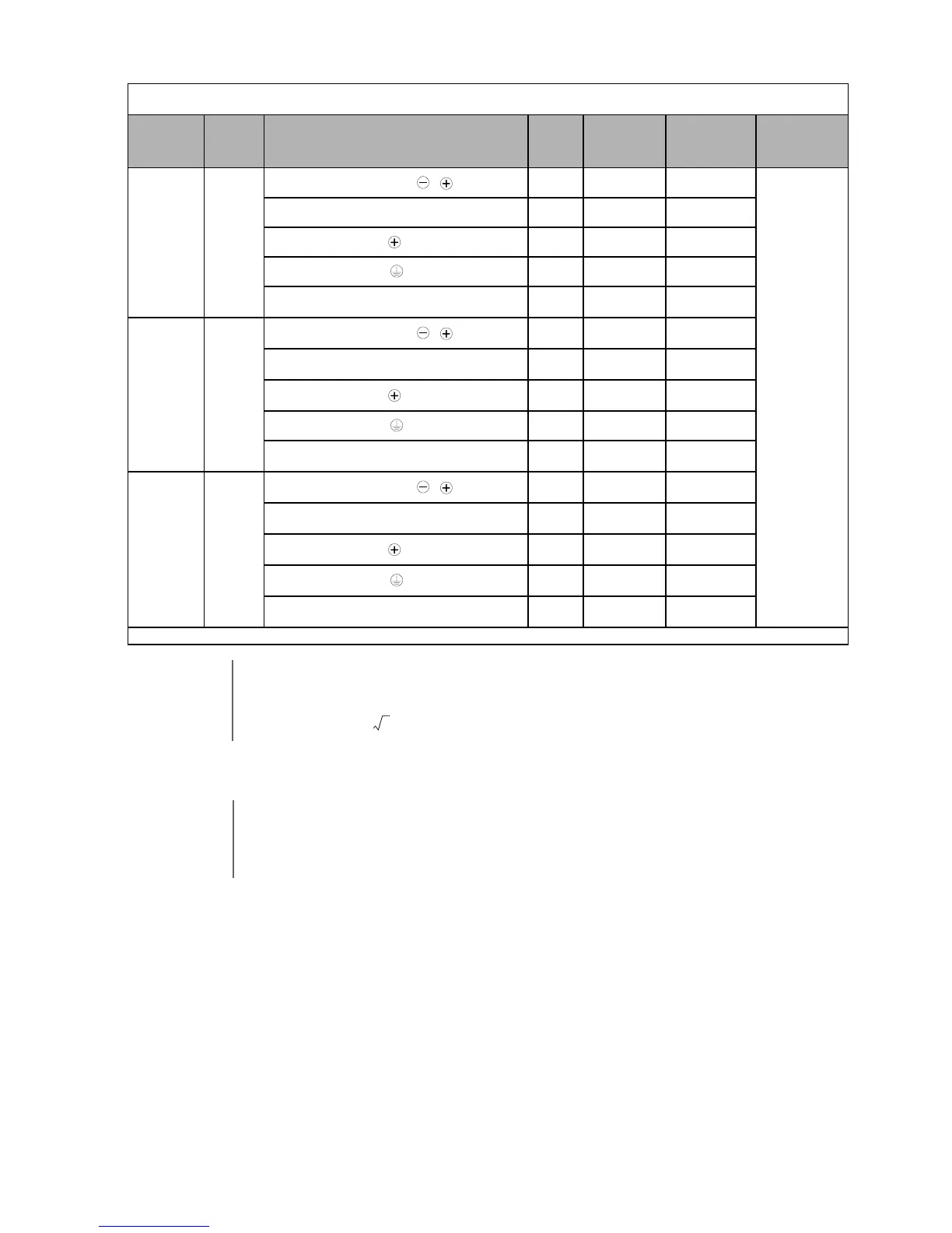
*Use 75°C copper wire or equivalent.
IMPORTANT
Determine the wire size for the main circuit so that line voltage drop is within 2% of the rated voltage. Line
voltage drop is calculated as follows:
Line voltage drop (V) =
x wire resistance (Ω/km) x wire length (m) x current (A) x 10
-3
Table 2.2 480Vac Wire Sizes and Connector Specifications
Drive Model
CIMR-P7U
Nominal
Hp
Terminal Symbol
Termi nal
Screws
Clamping
Torque
lb. in.
(N•m)
Recommended
Wire Size AWG
(mm
2
)
Wire Type
3
WARNING
Prior to removing any protective cover or wiring any part of the Drive, remove all power sources, including
main input power and control circuit power. Wait a minimum of 5 minutes after power removal, before
removing any cover. The charge lamp located within the Drive should be off prior to working inside. Even if
the charge lamp is off, one must measure the AC input, output, and DC Bus potential to insure safe levels
prior to resuming work. Failure to adhere to this warning may result in personal injury or death.