10 Appendix
10-28
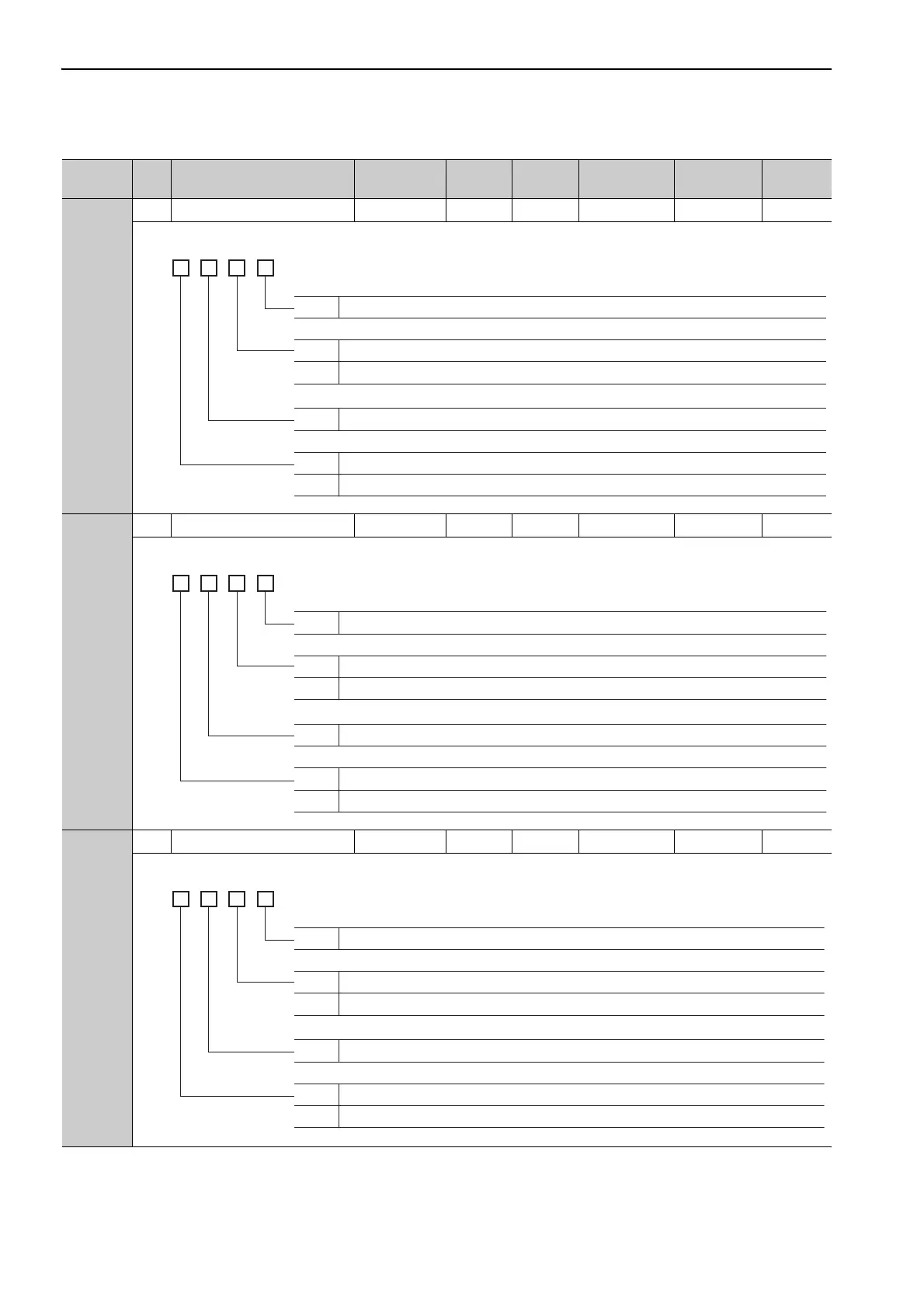
Pn82A
2 Option Field Allocation 1 0000 to 1E1E – 1813 After restart Setup
*1
Pn82B
2 Option Field Allocation 2 0000 to 1F1F – 1D1C After restart Setup
*1
Pn82C
2 Option Field Allocation 3 0000 to 1F1F – 1F1E After restart Setup
*1
∗1. For details, refer to the
Σ
-V Series/DC Power Input
Σ
-V Series/
Σ
-V Series for Large-Capacity Models User’s Man-
ual MECHATROLINK-II Commands (Manual No.: SIEP S800000 54).
(cont’d)
Parameter
No.
Size
Name
Setting
Range
Units
Factory
Setting
When
Enabled
Classification
Reference
Section
4th
digit
3rd
digit
2nd
digit
1st
digit
n.
0 to E ACCFIL bit position
0
1
Disables ACCFIL bit allocation.
Enables ACCFIL bit allocation.
0 to E GSEL bit position
0
1
Disables GSEL bit allocation.
Enables GSEL bit allocation.
4th
digit
3rd
digit
2nd
digit
1st
digit
n.
0 to F V_PPI bit position
0
1
Disables V_PPI bit allocation.
Enables V_PPI bit allocation.
0 to F P_PI_CLR bit position
0
1
Disables P_PI_CLR bit allocation.
Enables P_PI_CLR bit allocation.
4th
digit
3rd
digit
2nd
digit
1st
digit
n.
0 to F P_CL bit position
0
1
Disables P_CL bit allocation.
Enables P_CL bit allocation.
0 to F N_CL bit position
0
1
Disables N_CL bit allocation.
Enables N_CL bit allocation.