3 Wiring and Connection
3.1.2 Using a Standard Power Supply (Single-phase 100 V, Three-phase 200 V, or Three-phase 400 V)
3-4
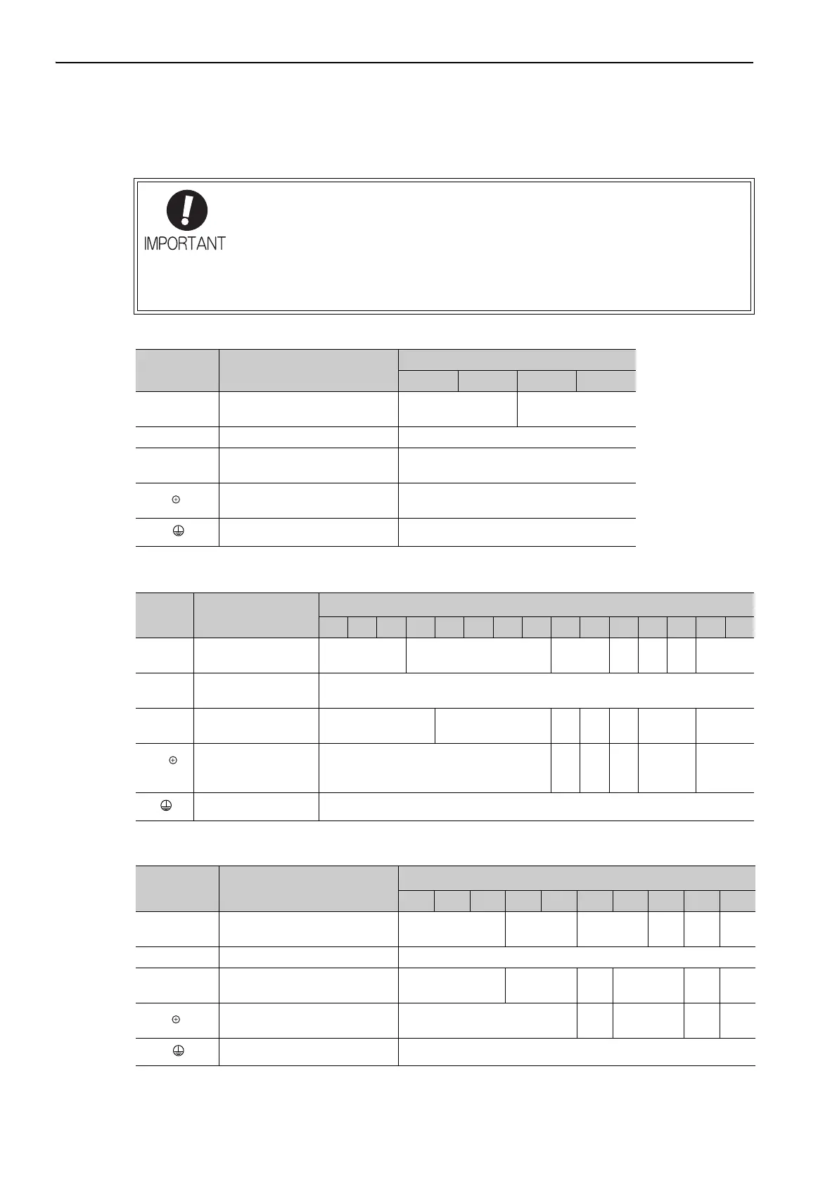
(2) Main Circuit Wires
This section describes the main circuit wires for SERVOPACKs.
Single-phase, 100 V
Three-phase, 200 V
Three-phase, 400 V
• The specified wire sizes are for use when the three lead cables are bundled and when
the rated electric current is applied with a surrounding air temperature of 40°C.
• Use a wire with a minimum withstand voltage of 600 V for the main circuit.
• If cables are bundled in PVC or metal ducts, take into account the reduction of the
allowable current.
• Use a heat-resistant wire under high surrounding air or panel temperatures, where
polyvinyl chloride insulated wires will rapidly deteriorate.
Termin a l
Symbols
Name
SGDV-F
R70 R90 2R1 2R8
L1, L2
Main circuit power input termi-
nals
HIV1.25 HIV2.0
L1C, L2C Control power input terminals HIV1.25
U, V, W
Servomotor connection termi-
nals
HIV1.25
B1/ , B2
External regenerative resistor
connection terminals
HIV1.25
Ground terminal HIV2.0 or larger
Termin a l
Symbols
Name
SGDV-A (Unit: mm
2
)
R70 R90 1R6 2R8 3R8 5R5 7R6 120 180 200 330 470 550 590 780
L1, L2,
L3
Main circuit power in-
put terminals
HIV1.25 HIV2.0 HIV3.5
HIV
5.5
HIV
8.0
HIV
14.0
HIV22.0
L1C, L2C
Control power input
terminals
HIV1.25
U, V, W
Servomotor connec-
tion terminals
HIV1.25 HIV2.0
HIV
3.5
HIV
5.5
HIV
8.0
HIV14.0 HIV22.0
B1/ ,
B2
External regenerative
resistor connection
terminals
HIV1.25
HIV
2.0
HIV
3.5
HIV
5.5
HIV8.0 HIV22.0
Ground terminal HIV2.0 or larger
Termin a l
Symbols
Name
SGDV-D (Unit: mm
2
)
1R9 3R5 5R4 8R4 120 170 210 260 280 370
L1, L2, L3
Main circuit power input termi-
nals
HIV1.25 HIV2.0 HIV3.5
HIV
5.5
HIV
8.0
HIV
14.0
24V, 0V Control power input terminals HIV1.25
U, V, W
Servomotor connection termi-
nals
HIV1.25 HIV2.0
HIV
3.5
HIV5.5
HIV
8.0
HIV
14.0
B1/ , B2
External regenerative resistor
connection terminals
HIV1.25
HIV
2.0
HIV3.5
HIV
5.5
HIV
8.0
Ground terminal HIV2.0 or larger