3.1 Main Circuit Wiring
3-9
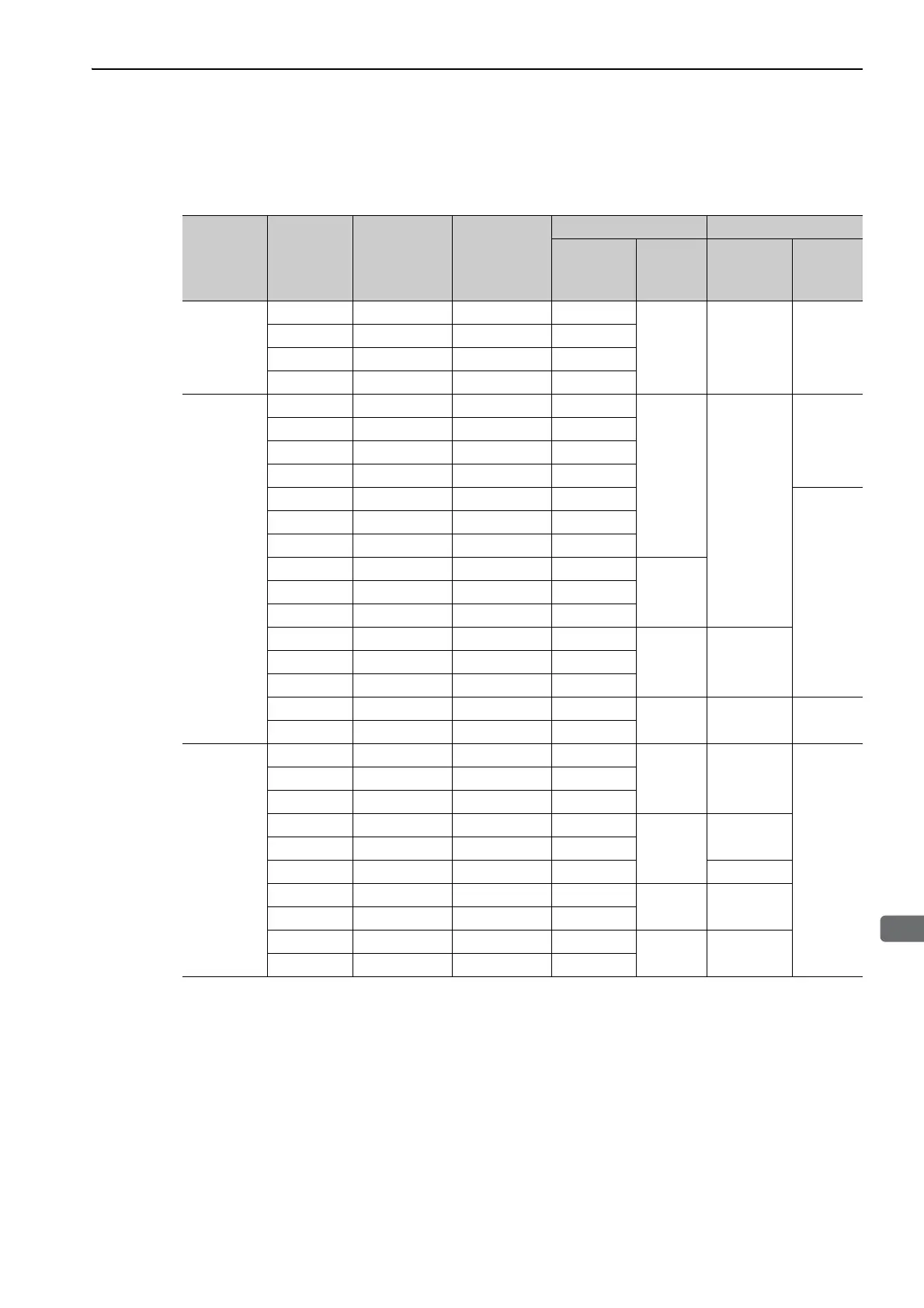
(5) How to Select Molded-case Circuit Breaker and Fuse Capacities
The following table shows the SERVOPACK’s current capacities and inrush current.
Use these values as a basis for selecting the molded-case circuit breaker and fuse.
Note 1. To comply with the EU low voltage directive, connect a fuse to the input side as protection against accidents
caused by short-circuits.
Select fuses or molded-case circuit breakers that are compliant with UL standards.
The table above also provides the net values of current capacity and inrush current. Select a fuse and a molded-
case circuit breaker which meet the breaking characteristics shown below.
• Main circuit, control circuit: No breaking at three times the current values shown in the table for 5 s.
• Inrush current: No breaking at the current values shown in the table for 20 ms.
Main
Circuit
Power
Supply
Maximum
Applicable
Servomotor
Capacity
[kW]
SERVOPACK
Model
SGDV-
Power Supply
Capacity per
SERVOPACK
[kVA]
Current Capacity Inrush Current
Main Circuit
[Arms]
Control
Circuit
[Arms]
Main Circuit
[A0-p]
Control
Circuit
[A0-p]
Single-
phase,
100 V
0.05 R70F 0.2 1.5
0.38 16.5 35
0.1 R90F 0.3 2.5
0.2 2R1F 0.7 5
0.4 2R8F 1.4 10
Three-
phase,
200 V
0.05 R70A 0.2 1.0
0.2
33
70
0.1 R90A 0.3 1.0
0.2 1R6A 0.6 2.0
0.4 2R8A 1 3.0
0.5 3R8A 1.4 3.0
33
0.75 5R5A 1.6 6.0
1.0 7R6A 2.3 6.0
1.5 120A 3.2 7.3
0.252.0 180A 4 9.7
3.0 200A 5.9 15
5.0 330A 7.5 25
0.3 65.56.0 470A 10.7 29
7.5 550A 14.6 37
11 590A 21.7 54
0.45 109 48
15 780A 29.6 73
Three-
phase,
400 V
0.5 1R9D 1.1 1.4
1.2 17
–
1.0 3R5D 2.3 2.9
1.5 5R4D 3.5 4.3
2.0 8R4D 4.5 5.8
1.4
34
3.0 120D 7.1 8.6
5.0 170D 11.7 14.5 57
6.0 210D 12.4 17.4
1.5 34
7.5 260D 14.4 21.7
11 280D 21.9 31.8
1.7 68
15 370D 30.6 43.4