2-6
IM MV1000-01E
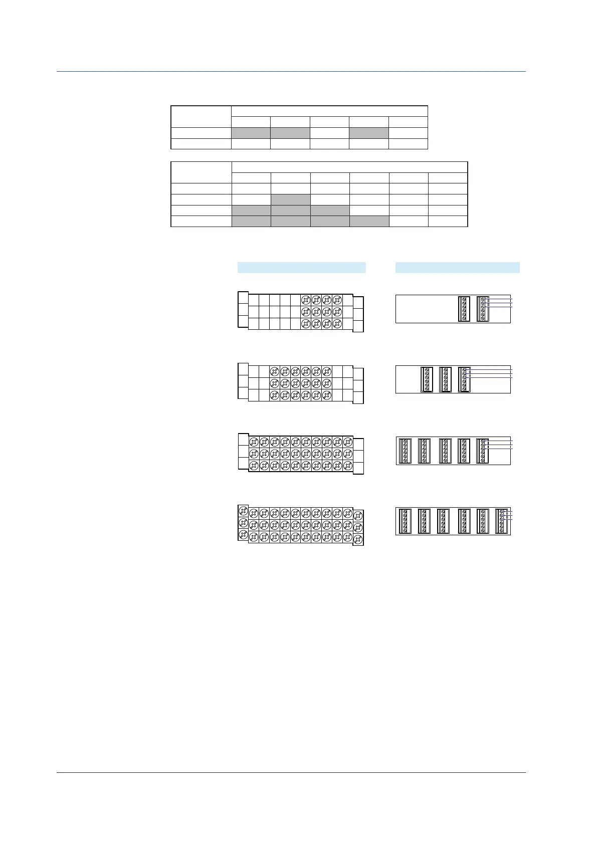
Input Terminal Block Channel Assignments
The following table shows which channels are assigned to which terminal blocks.
Input
terminalblock
MV1000 Channel Assignment
MV1004 MV1006 MV1008 MV1012 MV1024
1 1–4 1–12
2 1-4 1-6 5-8 1-12 13-24
Input
terminalblock
MV2000 Channel Assignment
MV2008 MV2010 MV2020 MV2030 MV2040 MV2048
1 1–4 1-10 1-10 1-10 1-10 1-12
2 5-8 11-20 11-20 11-20 13-24
3 21-30 21-30 25-36
4 31-40 37-48
This picture shows where the channel inputs are located on each terminal block.
+/A
/b
CH1
CH2
CH3
CH4
CH1
CH2
CH3
CH4
CH5
CH6
–/B
+/A
/b
–/B
CH5 CH3 CH1
CH6 CH4 CH2
CH3 CH1
CH4 CH2
/b
+/A
–/B
/b
+/A
–/B
Screw terminal
Input terminal block of
the MV1004, MV1008,
and MV2008.
MV1006 input
terminal block
Clamp terminal
CH1
CH2
CH3
CH4
CH5
CH6
CH7
CH8
CH9CH11
CH10CH12
+/A
/b
–/B
CH5 CH3 CH1
CH6 CH4 CH2
CH9 CH7
CH10
CH11
CH12
CH8
/b
+/A
–/B
Input terminal block of
the MV1012, MV1024,
and MV2048.
+/A
/b
CH1
CH2
CH3
CH4
CH5
CH6
CH7
CH8
CH9
CH10
–/B
CH5 CH3 CH1
CH6 CH4 CH2
CH9 CH7
CH10
CH8
/b
+/A
–/B
Input terminal block of
the MV2010, MV2020,
MV2030, and MV2040
2.2 Signal Input Terminal Wiring

 Loading...