2-7
IM MV1000-01E
Installation and Wiring
1
2
3
4
5
6
7
8
9
10
11
12
13
App
Index
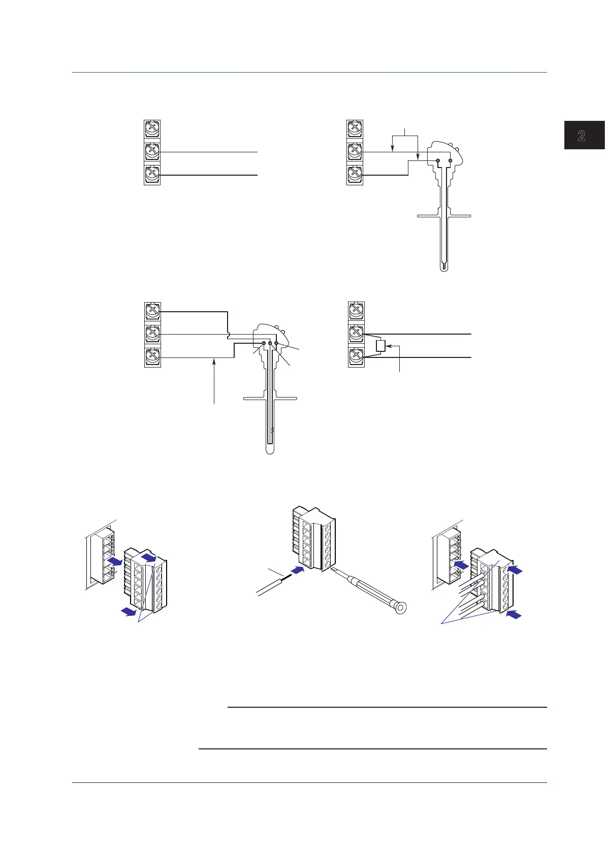
Screw Terminal Wiring
–
+
+
–
DC voltage input
TC input
DC voltage input/DI (ON/OFF) input
RTD input
DC current input
DC current input
Shunt resistor
Example: For 4 to 20 mA input, use a
shunt resistor of 250 Ω
–
+
–
+
–
+
A
B
b
Lead wire resistance per wire of
10 Ω or less. Make the resistance
of the three wires equal.
A
b
B
Compensating leadwire
±
0.1%.
Clamp Terminal Wiring
Remove the terminal block
Hold both ends of the terminal
block and pull straight.
Input signal wire
First, loosen the screw at the front using
a flat-blade screwdriver. Insert the input
signal wire into the slit on the left side of
the terminal block, and fasten the screw
at the front.
Recommended wire size
0.08 to 1.5 mm
2
(AWG28 to 16)
Recommended length
of stripped wire:
7 mm
Connect the wires
Flat-blade
screwdriver
Hold both ends of the terminal
block, align it with the connector,
and then push it in.
Connect the terminal block
Note
RTD input terminals A and B are isolated on each channel. Terminal b is shorted internally
across all channels. On models with the /N1 option (Cu10, Cu25 RTD input/3-wire isolated
RTD) or the /N2 option (3-wire isolated RTD), terminal b is also isolated on each channel.
2.2 Signal Input Terminal Wiring

 Loading...