4-7
IM 760301-01E
4
Measurement Conditions
Explanation
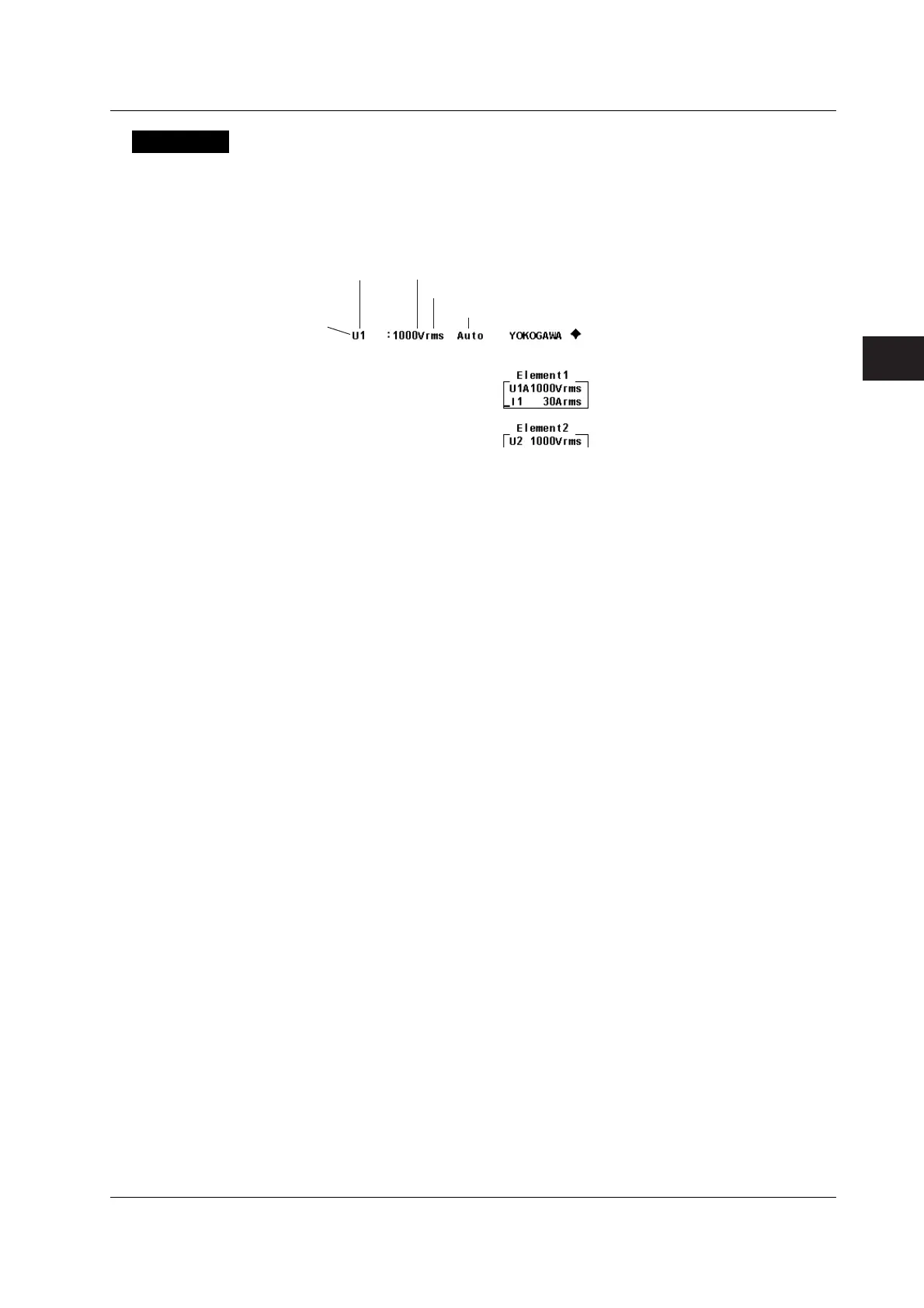
• Display Position of the Target Element and Specified Range
When a voltage or current range selection key is pressed, the element is displayed in
the voltage or current range indicator (7-segment LED) and at the upper-right corner
of the screen.
Example of the display at the upper-right corner
Element
Voltage
Voltage range
Voltage mode
Displayed when set to auto range.
• Selecting the Target Element to Be Configured
Only the indicators of installed elements illuminate sequentially. When the
independent setting of input elements is OFF, the element switches for each wiring
unit according to the wiring system.
• Setting the Voltage and Current Ranges
There are two types of ranges, fixed and auto.
• Fixed Range
The range is set in reference to the RMS value of the input signal.
• Voltage Range
• When the crest factor is set to 3
Select 15 V, 30 V, 60 V, 100 V, 150 V, 300 V, 600 V, or 1000 V.
• When the crest factor is set to 6
Select 7.5 V, 15 V, 30 V, 50 V, 75 V, 150 V, 300 V, or 500 V.
• Current range
• 2-A input element
• When the crest factor is set to 3
Select 5 mA, 10 mA, 20 mA, 50 mA, 100 mA, 200 mA, 500 mA, 1 A, or 2 A.
• When the crest factor is set to 6
Select 2.5 mA, 5 mA, 10 mA, 25 mA, 50 mA, 100 mA, 250 mA, 500 mA, or
1 A.
• 30-A input element
• When the crest factor is set to 3
Select 500 mA, 1 A, 2 A, 5 A, 10 A, 20 A, or 30 A.
• When the crest factor is set to 6
Select 250 mA, 500 mA, 1 A, 2.5 A, 5 A, 10 A, or 15 A.
4.3 Setting the Measurement Range for Direct Input
 Loading...


