4-20 IM 760301-01E
Explanation
The measurement period is determined by the data update rate and the synchronization
source specified by carrying out the procedure in this section. For details, see appendix 6.
During normal measurement, the numeric data is measured/computed from the data
sampled within the measurement period.
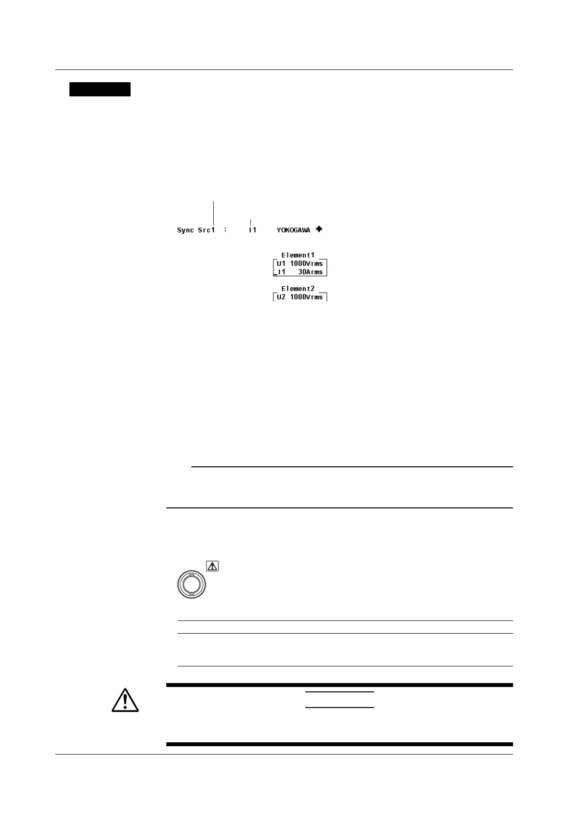
• Display Position of the Target Element and Synchronization Source
The target element and the synchronization source are displayed in the upper right
corner of the screen when SYNC SOURCE is pressed.
Target element (displayed as 1-4 when all elements are selected collectively)
Synchronization source (example in which
the current of Element 1 is specified)
• Selecting the Target Element to Be Specified
Only the indicators of installed elements illuminate sequentially. When the independent
setting of input elements is OFF, the element switches according to the wiring system.
All elements can also be selected collectively.
• Setting the Synchronization Source
You can select which input signal will be the synchronization source (the zero-
crossing point of the input signal to which the measurement period is synchronized)
for each element or all elements collectively. Select the signal to be the
synchronization source from the choices below. The selectable items vary depending
on the installed elements.
U1, I1, U2, I2, U3, I3, U4, I4, Ext Clk (external clock), and None
Note
If you specify no synchronization source by selecting “None,” the entire sampled data within the data
update interval is the data used to determine the numeric data. When measuring DC signals, this
method can be used to prevent errors in the detection of the measurement period caused by noise.
• When Setting the Synchronization Source to Ext Clk
Apply a clock signal to the external clock input connector (EXT CLK) on the rear panel
according to the following specifications.
EXT. CLK
• Ext Clk Specifications
Item Specifications
Connector type BNC connector
Input level TTL
Input waveform 50% duty ratio rectangular wave
CAUTION
Applying a voltage outside the range of 0 to 5 V to the external clock input
connector (EXT CLK) can damage the instrument.
4.7 Setting the Measurement Period
 Loading...


