4-21
IM 760301-01E
4
Measurement Conditions
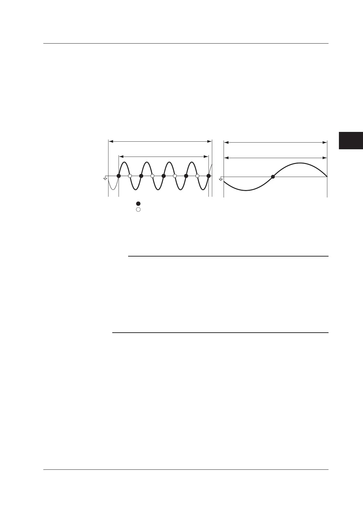
• Measurement Period
• When the data update rate is 50 ms, 100 ms, 5 s, 10 s, or 20 s
You must set the measurement period. The measurement period is set between
the first point where the synchronization source crosses the level zero point (center
of the amplitude) on the rising slope (or falling slope) within the data update period
and the last point where the synchronization source crosses the level zero point
(center of the amplitude) on the rising slope (or falling slope) within the update
period. If there is one or no zero crossing in the data update interval, the
measurement period is set equal to the data update interval. For details, see
appendix 6.
Data update interval
Measurement period
Synchronization
source
Rising edge zero crossing
Falling edge zero crossing
Data update interval
Measurement period
• When the data update rate is 250 ms, 500 ms, 1 s, or 2 s
You do not have to set the measurement period. The measurement period is equal
to the data update interval.
Note
• The measurement period for the numeric data of the maximum value (Peak) for voltage and
current is the entire span within the data update period regardless of the settings above.
Therefore, the measurement period for the measurement functions U+pk, U-pk, I+pk, I-pk,
CfU, CfI, FfU, and FfI that are determined from the maximum value of the voltage and current
is also the entire span within the data update period.
• The measured value may fluctuate or may not be correct if the synchronization source is not
set correctly. Refer to appendix 6 when setting the synchronization source.
• For the list of measurement period (synchronization source) settings of all input elements, see
section 3.17, “Displaying the Setup Parameter List.” You can change the measurement period
(synchronization source) with the list displayed.
4.7 Setting the Measurement Period
 Loading...


