9-16 IM 760301-01E
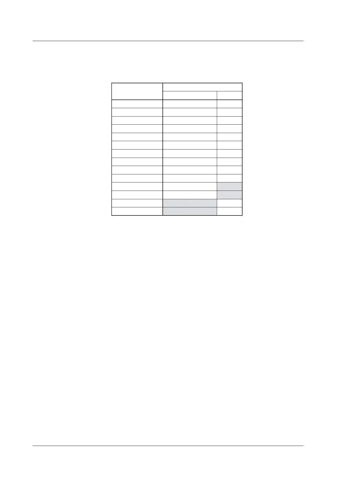
• Relationship between the Waveform Sampling Data That Can Be Saved and
Measurement Modes
There are limitations on waveform sampling data that can be saved depending on
the measurement mode as indicated below:
NoFFT2
*2
NoFTT1
*2
NoYesMath2
*2
NoYesMath1
*2
YesTorque
*1
YesYesSpeed
*1
YesYesI4
YesYesU4
YesYesI3
YesYesU3
YesYesI2
YesYesU2
YesYesI1
YesYesU1
FFT
*2
Waveform Computation
*2
Waveform Display Data
Measurement Mode
Yes
Yes
*1 Applicable only to products with the motor evaluation function (motor version).
*2 Applicable only to products with the advanced computation (/G6 option).
Yes
• Selecting the Data Type
Select the data type from below. The extension is automatically added.
•Binary
• The following two files are created in the directory.
• Waveform display data file (.wvf)
• ASCII header file (.hdr)
• Waveform display data is saved in binary format.
• For details on the ASCII header file, see appendix 3.
• Neither file can be loaded into the WT3000.
• ASCII
• Saved in ASCII format.
• The file can be used on your PC for analysis.
• The file cannot be loaded into the WT3000.
• Float
• Saved in 32-bit floating format.
• The file cannot be loaded into the WT3000.
9.3 Saving Setup Parameters, Waveform Display Data, Numeric Data, Waveform Sampling Data
 Loading...


