10-15
IM 760301-01E
10
Other Functions
Explanation
With the master instrument outputting measurement start signal and the slave instrument
receiving the signal, synchronized measurement between two instruments is achieved.
• External Start Signal Input/Output Connector
Connect the external start signal input/output connectors on the rear panel between
the master and slave instruments using BNC cables (sold separately).
MEAS. START
Item Specifications Note
Connector type BNC connector Common to master and slave
I/O level TTL Common to master and slave
Output logic (negative logic), falling edge Applies to the master
Measurement start delay time (1 µs +1 sample interval) Applies to the master
Output hold time Low level, 500 ns or more Applies to the master
Input logic (negative logic), falling edge Applies to the slave
Minimum pulse width Low level, 500 ns or more Applies to the slave
Input delay time During HOLD ON Applies to the slave
(1 µs + 1 sample interval)
During HOLD OFF Applies to the slave
Within (63 ns + 1 sample period)
Note
The master and slave conditions in which synchronized measurement is not possible are as
follows:
• The data update rate differs between the master and slave.
• During real-time integration mode or real-time store mode.
Carry out the hold operation according to the procedure below during synchronized measurement.
• Hold ON: Turn the hold function ON from the WT3000 set to master.
• Hold OFF: Turn the hold function OFF from the WT3000 set to slave.
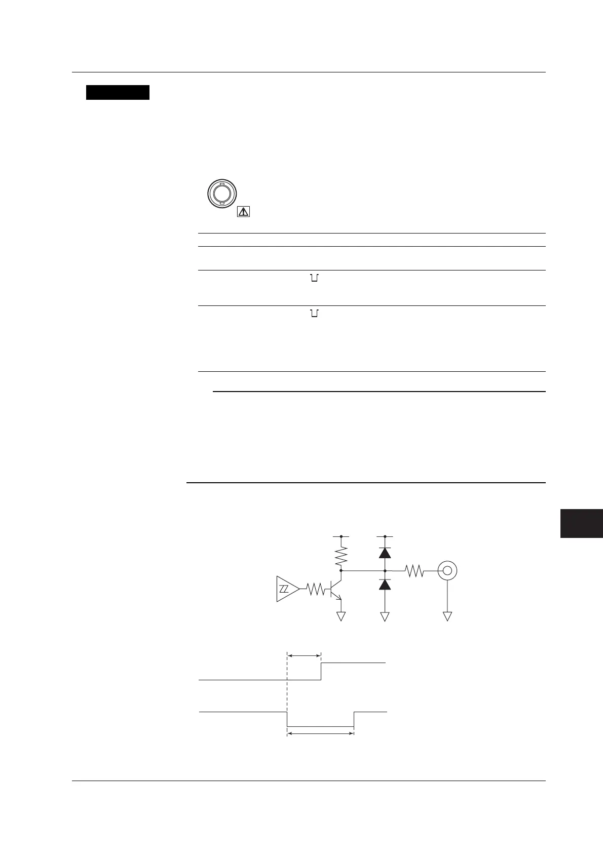
• Output Circuit for the External Start Signal and Time Chart
Start output
signal
100 Ω
10 kΩ
+5 V
+5 V
Start output
signal
Measurement start
Output hold time
Measurement start delay time
10.9 Master/Slave Synchronization Measurement
 Loading...


