10-16 IM 760301-01E
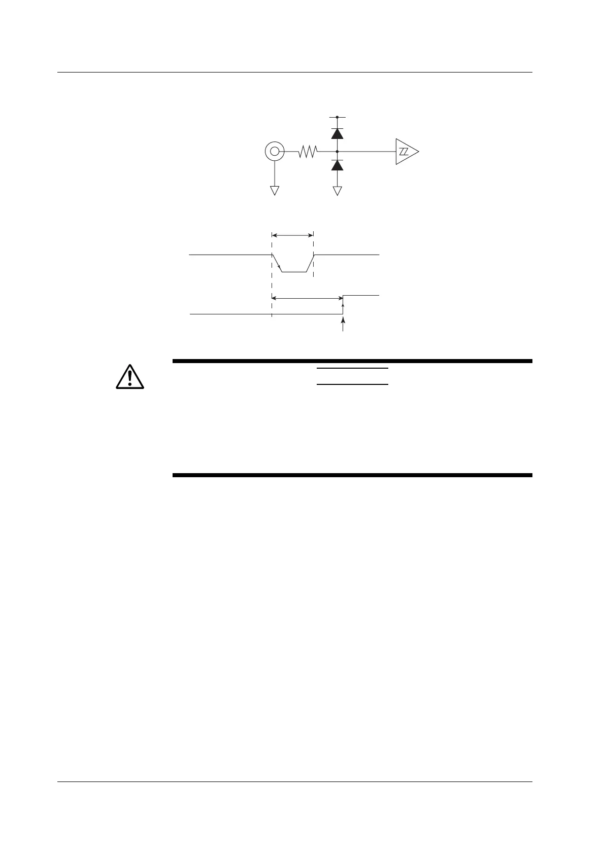
• Input Circuit for the External Start Signal and Time Chart
Start input
signal
Start input
signal
100 Ω
+5 V
Minimum pulse width
Input delay time
Measurement start
Trigger occurrence
CAUTION
• When the instrument is set to master, do not apply external voltage to the
external start signal input/output connector (START). If you do, the instrument
may malfunction.
• Applying a voltage outside the 0 to 5 V range to the external start signal
input/output connector when the instrument is set to slave may cause damage
to the instrument.
• Limitations on the Synchronized Measurement by Measurement Modes
Synchronized measurement cannot be used in the following measurement modes.
• Wide bandwidth harmonic measurement mode
• IEC harmonic measurement mode
• Waveform computation mode
• FFT mode
• Voltage fluctuation and flicker measurement mode
• Cycle-by-cycle measurement mode
10.9 Master/Slave Synchronization Measurement

 Loading...


