App-3
IM 760301-01E
App
Appendix
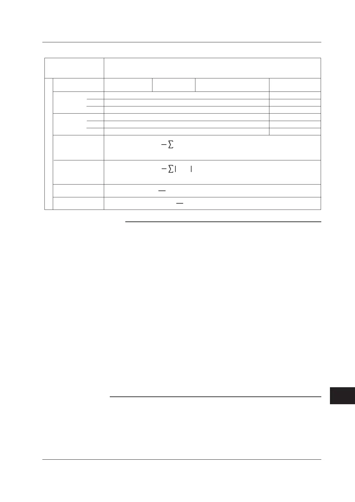
Measurement Functions
during Normal
Measurement
Σ
function
(Table 3/3)
Single-phase,
two-wire 1P3W
Three-phase,
three-wire 3P3W
Three-phase, three-wire (three-voltage,
three-current)
3P3W (3V3A)
Three-phase,
four-wire 3P4W
PΣ
SΣ
WPΣ [Wh]
Wiring system
qΣ [Ah]
WPΣ
WP+Σ
WP–Σ
qΣ
q+Σ
q–Σ
WP1 + WP2
WP+1 + WP+2
WP–1 + WP–2
q1 + q2
q+1 + q+2
q–1 + q–2
WP1 + WP2 + WP3
WP+1 + WP+2 + WP+3
WP–1 + WP–2 + WP–3
q1 + q2 + q3
q+1 + q+2 + q+3
q–1 + q–2 + q–3
λΣ
WS
Σ
[VAh]
WQΣ [varh]
SΣ(n) is the n
th
apparent power Σ function. N is the number of data updates.
QΣ(n) is the n
th
reactive power Σ function. N is the number of data updates.
Method of Determination, Equation
For details on the symbols in the equation, see the Note on page App-3.
COS
-1
(
)
PΣ
SΣ
φΣ [°]
SΣ(n)
•
Time
n = 1
N
1
N
QΣ(n)
•
Time
n = 1
N
1
N
Note
• u(n) denotes the instantaneous voltage (sampled data of the voltage signal).
• i(n) denotes the instantaneous current (sampled data of the current signal).
• AVG[ ] computes the average on the sampled data in the brackets over the measurement
period. There are two ways of computing the average, and either one is selected depending
on the data update interval. For details on the measurement period and the averaging
method, see appendix 7, “Data Update Rate and Computing Equation.”
•PΣA and PΣB denote the active power of the wiring units ΣA and ΣB, respectively. The
assignment of input elements to wiring units ΣA and ΣB is determined by the number of input
elements that are installed in the WT3000 and the selected wiring system pattern. For details,
see section 2.3.
• The numbers 1, 2, and 3 in the equations UΣ, IΣ, PΣ, SΣ, QΣ, PcΣ, WPΣ, and qΣ indicate the
case when input elements 1, 2, and 3 are set to the wiring system shown in the table. If
elements 2, 3, and 4 are set to the wiring system shown in the table, replace the numbers 1,
2, and 3 with 2, 3, and 4, respectively.
• Equation TYPE 3 for SΣ and QΣ can be selected only on models with the advanced
computation (/G6) or the harmonic measurement (/G5) option.
• S, Q, λ, and φ on the WT3000 are derived through the computation of the measured values of
voltage, current, and active power (except Q is calculated directly from the sampled data
when TYPE3 is selected ). If distorted signal is input, the value obtained on this instrument
may differ from that obtained on other instruments using a different measurement principle.
• For Q [var] computation, when the current leads the voltage, the Q value is displayed as a
negative value; when the current lags the voltage, the Q value is displayed as a positive
value. The value of QΣ may be negative, because it is calculated from Q of each element
including the sign.
For details on the measurement functions of the motor evaluation function, see
section 1.10 in the
Expansion Function User’s Manual IM760301-51E
.
For details on the measurement functions of harmonic measurement, see section 7.11
in the
Expansion Function User’s Manual IM760301-51E
.
Appendix 1 Symbols and Determination of Measurement Functions
 Loading...


