2-8 IM 760301-01E
Measurement Period
• Measurement Functions of Normal Measurement
The measurement period varies depending on the data update rate (see section 2.3)
as follows:
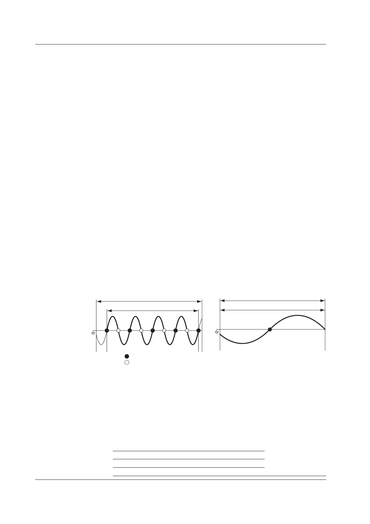
• When the Data Update Rate Is 50 ms, 100 ms, 5 s, 10 s, or 20 s
• The measurement period is set between the first point where the reference input
signal (synchronization source) crosses the level zero point (center of the
amplitude) on the rising slope (or falling slope)
*1
within the data update interval
*2
and the last point where the synchronization source crosses the level zero point
(center of the amplitude) on the rising slope (or falling slope) within the data
update interval. However, the measurement period for determining the numeric
data of the peak voltage or peak current is the entire span within the data
update interval. Therefore, the measurement period for the measurement
functions U+pk, U-pk, I+pk, I-pk, CfU, and CfI that are determined from the
maximum value of the voltage and current is also the entire span within the data
update period.
• The rising or falling edge is automatically selected for the one that allows the
interval to be longer.
• If the number of rising slope or falling slope is less than or equal to 1 within the
data update interval, the measurement period is set to the entire span within the
data update interval.
• You can select which input signal will be the synchronization source
(synchronized to the zero-crossing point of the input signal) for each element.
You can set the synchronization source signal to the voltage, current, or external
clock that is input to the element.
• For details, see appendix 6.
*1 Trigger slope refers to the movement of the signal from a low level to a high level (rising
edge) or from a high level to a low level (falling edge).
*2 The data update interval is the interval by which the data is sampled for determining the
measurement functions. This is equivalent to the value you can specify in “Data Update
Rate” of section 2.3.
Data update interval
Measurement period
Synchronization
source
Rising edge zero crossing
Falling edge zero crossing
Data update interval
Measurement period
• When the data update rate is 250 ms, 500 ms, 1 s, or 2 s
The measurement period is within the data update interval.
• Measurement Functions of Harmonic Measurement
The measurement period is the first 9000 points from the beginning of the data update
interval at the harmonic sampling frequency.
• FFT
The measurement period is over the number of FFT points (200,000 points or 20,000
points) at a sampling frequency of 200 KHz. Thus, the measurement period is as
follows:
Number of Computed Points Measurement Period
200,000 1 s
20,000 100 ms
2.2 Measurement Modes and Measurement Functions
 Loading...


