2-9
IM 760301-01E
2
Faunctional Description
2.3 Measurement Conditions
Number of Installed Input Elements and Wiring Systems «For procedures, see section 4.1.»
Wiring System
• There are five wiring systems available on the WT3000.
1P2W: Single-phase, two-wire system
1P3W: Single-phase, three-wire system
3P3W*: Three-phase, three-wire system
3P4W: Three-phase, four-wire system
3P3W* (3V3A): Three voltage, three current system
* In this manual, the symbolic expression 3P3W is used to indicate both three-phase, three-
wire system and three-voltage, three-current system. To differentiate between the two,
three-voltage, three-current system is expressed as 3P3W (3V3A).
• Limitations are placed on the wiring systems that can be selected depending on the
number of input elements that are installed in the instrument.
Wiring Unit
A wiring unit refers to a set of two or three input elements of the same wiring system that
are grouped. Up to two wiring units can be defined, each represented by the symbol ΣA
and ΣB.
For example, “UrmsΣA” represents the true rms value of the average of the voltage of
the input elements that are assigned to wiring unit ΣA
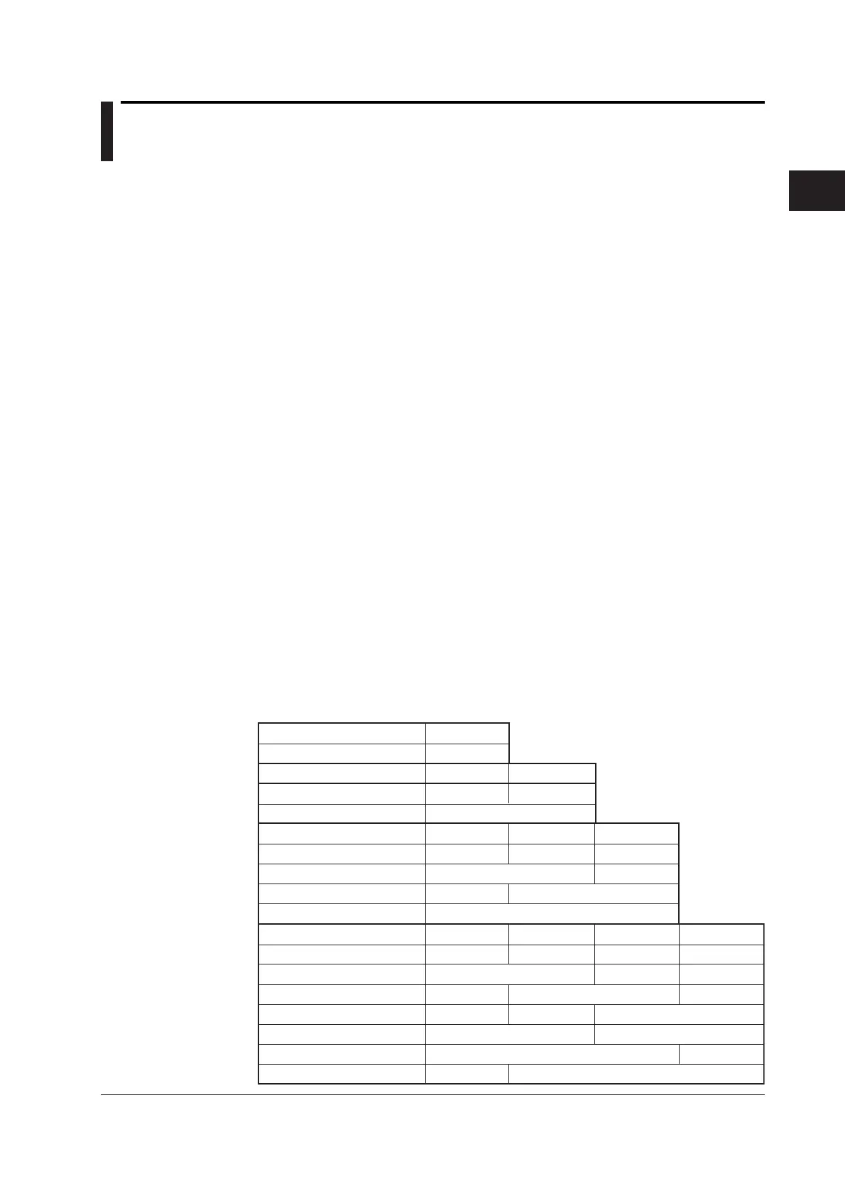
Wiring System Pattern
• The following table shows the relationship between the number of installed input
elements, the selectable wiring system patterns, and the assignment of input
elements to wiring units ΣA or ΣB.
For example, there are seven wiring system patterns on a WT3000 that has four input
elements installed.
• The input element assignment to wiring units ΣA or ΣB is determined from the wiring
system pattern. This allows Σ functions of voltage, current, active power, apparent
power, reactive power, power factor, phase difference, and other parameters to be
determined. For the relationship between the wiring system and the determination of
the Σ function, see appendix 1.
Installed input elements
Wiring system Pattern 1
1
1P2W
Installed input elements
Wiring system Pattern 1
Wiring system Pattern 2
1
1P2W
2
1P2W
1P3W or 3P3W: ΣA
Installed input elements
Wiring system Pattern 1
Wiring system Pattern 2
Wiring system Pattern 3
Wiring system Pattern 4
1
1P2W
2
1P2W
3
1P2W
1P2W
1P2W
1P2W
1P2W
1P3W or 3P3W(3V3A): ΣA
1P3W or 3P3W: ΣA
1P3W or 3P3W: ΣA
P3W or 3P3W: ΣB
1P3W or 3P3W: ΣA
1P3W or 3P3W(3V3A): ΣA
1P3W or 3P3W: ΣB
3P4W or 3P3W(3V3A): ΣA
3P4W or 3P3W(3V3A): ΣA
3P4W or 3P3W(3V3A): ΣA
Installed input elements
Wiring system Pattern 1
Wiring system Pattern 2
Wiring system Pattern 3
Wiring system Pattern 4
Wiring system Pattern 5
Wiring system Pattern 6
Wiring system Pattern 7
1
1P2W
1P2W
1P2W
2
1P2W
1P2W
3
1P2W
1P2W
4
1P2W
1P2W
1P2W
 Loading...


