2-19
IM 760301-01E
2
Faunctional Description
• TYPE 3 (The Method Used by Harmonic Measurement Mode on the WT1600 and
PZ4000)
The reactive power of each phase is calculated directly using equation (2). The three-
phase apparent power is calculated using equation (4). This computing equation can
be selected on models with the advanced computation (/G6) or harmonic
measurement (/G5) option.
Active power for three-phase, four-wire system PS = P1 + P2 + P3
Apparent power for three-phase, four-wire system
SΣ =
PΣ
2
+ QΣ
2
Reactive power for three-phase, four-wire system QS = Q1 + Q2 + Q3
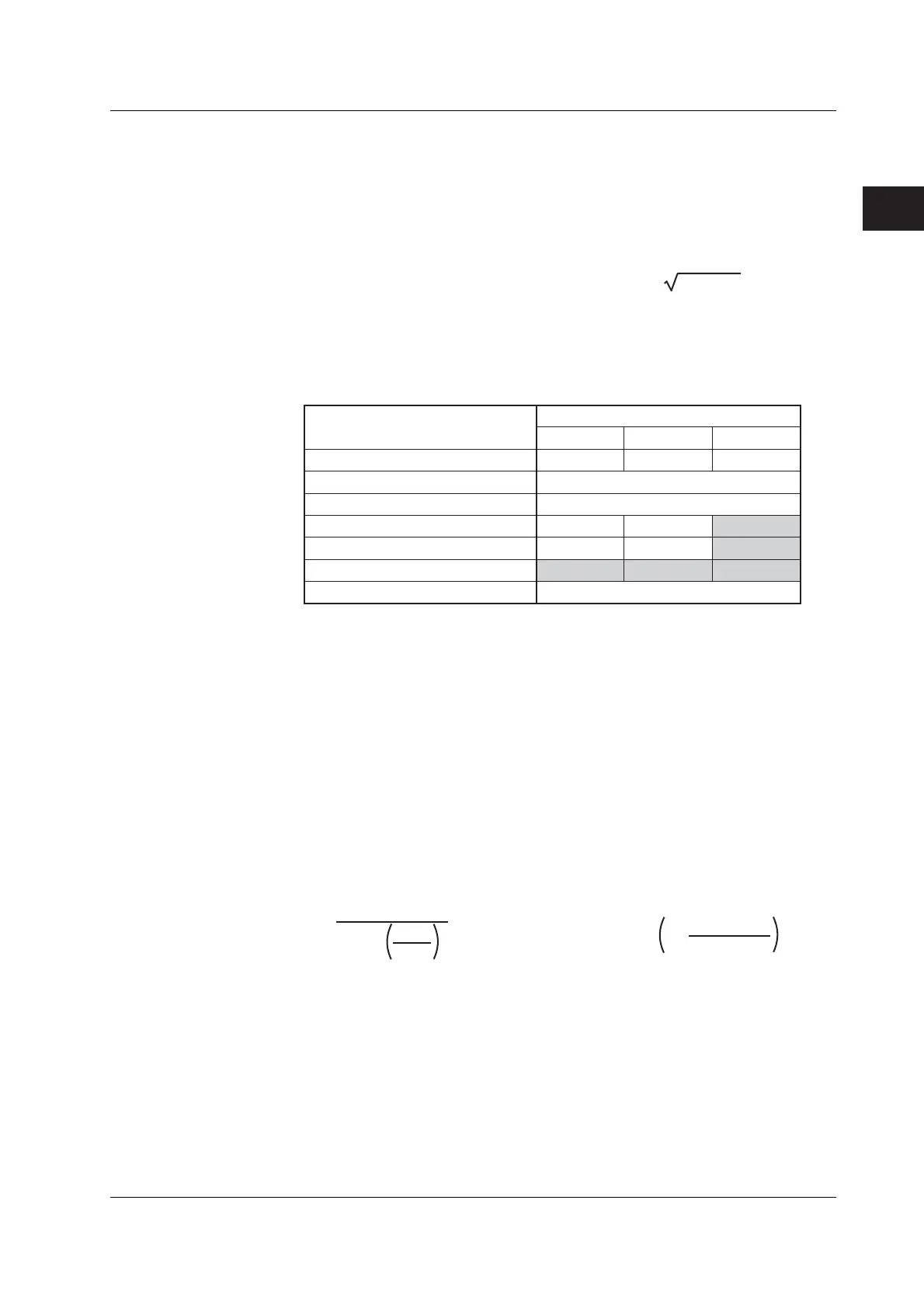
• Measurement Mode and Computing Equation
The computing equations that can be selected in each measurement mode are as
follows:
Normal Measurement Yes Yes Yes
Wide Bandwidth Harmonic*
2
Fixed to TYPE3*
3
IEC Harmonic*
2
Fixed to TYPE3*
3
Waveform Computation Yes Yes No*
4
FFT Yes Yes No*
4
Voltage Fluctuations and Flicker*
2,
*
5
No No No
Cycle by Cycle*
2
Fixed to TYPE2*
6
Yes: Selectable.
No: Not selectable.
*1 Selectable only on models with the advanced computation (/G6) option.
*2 The setup menu of the equations of S and Q is not displayed.
*3 If TYPE1 or 3 is selected and you select wide bandwidth harmonic measurement mode or IEC harmonics mode,
the equation switches to TYPE3.
*4 If TYPE3 is selected and you select waveform computation mode or FFT mode, the equation switches to TYPE1.
*5 S and Q are not measured in voltage fluctuation and flicker measurement mode. Thus, the S and Q equation
settings are invalid.
*6 If TYPE1 or 3 is selected and you select cycle-by-cycle measurement mode, the equation switches to TYPE2.
S and Q Equations
TYPE 1 TYPE 2 TYPE 3*
1
Measurement Mode
Corrected Power «For procedures, see section 5.9.»
Depending on the applicable standard, when the load that is connected to the potential
transformer is extremely small, the active power of the potential transformer that is
measured needs to be compensated. In such cases, set the compensating equation and
the coefficient.
IEC76-1(1976), IEEE C57.12.90-1993 IEC76-1(1993)
P
P
1
+ P
2
Urms
Umn
2
Pc =
P
Umn – Urms
Umn
1 +
Pc =
Pc: Corrected Power
P: Active power
Urms: True rms voltage
Umn: Voltage (rectified mean value calibrated to the rms value)
P
1
, P
2
: Coefficient as defined in the applicable standard
2.5 Computation
 Loading...


