3-19
IM 760301-01E
3
Before Starting Measurements
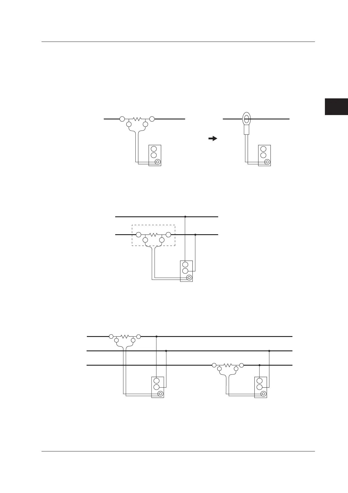
The following wiring examples are for connecting shunt-type current sensors. When
connecting a clamp-type current sensor that outputs voltage, substitute the shunt-type
current sensor with the clamp-type. In addition, the assignment of elements to the input
terminals in the following figure varies depending on the number of installed input
elements. For details, see “Number of Installed Input Elements and Wiring Systems” in
section 2.3, “Measurement Conditions.”
Shunt-type current sensor
±
I
OUT LOUT H
External current sensor
input connector
(EXT)
Input terminal
U
±
External current sensor
input connector
(EXT)
Input terminal
U
±
Clamp-type current sensor
that outputs voltage
Wiring Example of a Single-Phase, Two-Wire System (1P2W) Using a Shunt-Type
Current Sensor
SOURCE
LOAD
Earth side
Shunt-type current sensor
±
I
OUT L OUT H
External current sensor
input connector
(EXT)
Input terminal
U
±
Wiring Example of a Single-Phase, Three-Wire System (1P3W) Using a Shunt-Type
Current Sensor
SOURCE LOAD
±I
OUT L
OUT H
±
I
OUT L
OUT H
N
External current sensor
input connector
(EXT)
Input terminal 1
U
±
External current sensor
input connector
(EXT)
Input terminal 2
U
±
3.10 Wiring the Circuit under Measurement When Using the Current Sensor

 Loading...


