3-20 IM 760301-01E
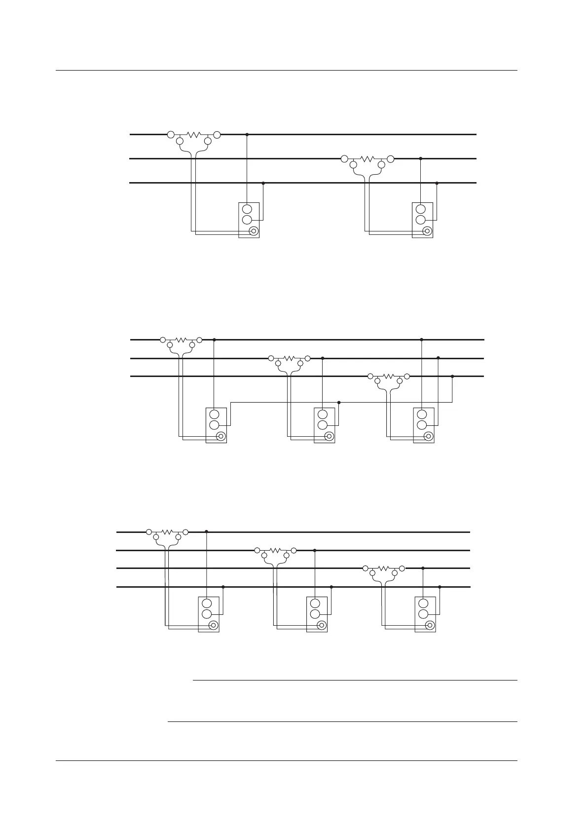
Wiring Example of a Three-Phase, Three-Wire System (3P3W) Using a Shunt-Type
Current Sensor
SOURCE LOAD
±I
OUT L
OUT H
±
I
OUT L
OUT H
R
S
T
External current sensor
input connector
(EXT)
Input terminal 1
U
±
External current sensor
input connector
(EXT)
Input terminal 2
U
±
Wiring Example of a Three-Phase, Three-Wire System (Three-Voltage, Three-Current
System) [3P3W (3V3A)] Using a Shunt-Type Current Sensor
SOURCE
LOAD
±I
OUT L
OUT H
±
I
OUT L
OUT H
R
S
T
±
I
OUT L
OUT H
External current sensor
input connector
(EXT)
Input
terminal 1
U
±
External current sensor
input connector
(EXT)
Input
terminal 2
U
±
External current sensor
input connector
(EXT)
Input
terminal 3
U
±
Wiring Example of a Three-Phase, Four-Wire System (3P4W) Using a Shunt-Type
Current Sensor
SOURCE LOAD
±I
OUT L
OUT H
I
OUT L
OUT H
R
S
T
N
±
I
OUT L
OUT H
External current sensor
input connector
(EXT)
Input
terminal 1
U
±
External current sensor
input connector
(EXT)
Input
terminal 2
U
±
External current sensor
input connector
(EXT)
Input
terminal 3
U
±
±
Note
For the relationship between the wiring systems and the method of determining the measured
values or computed values, see Appendix 1, “Symbols and Determination of Measurement
Functions.”
3.10 Wiring the Circuit under Measurement When Using the Current Sensor
 Loading...


