3-22 IM 760301-01E
Note
• After wiring, the wiring system must be selected. See section 4.1, “Selecting the Wiring
System.”
• The thick lines on the wiring diagrams are the sections where the current flows. Use
appropriate wires that are suitable for the current.
• Make sure you have the polarities correct when making the connections. Otherwise, the
polarity of the measurement current will be reversed and correct measurements cannot be
made. Be especially careful when connecting the clamp type current sensor, because it is
easy to reverse the connection.
• The scaling function can be used to transform the input signal to data that correspond to
direct measurements. For the setup procedure, see section 4.5, “Setting the Scaling Function
When Using the VT/CT.”
• Note that the frequency and phase characteristics of the VT or CT affect the measured data.
• For safety reasons, this section indicates wiring diagrams in which the common terminals (+/–)
of the secondary side of the VT or CT are grounded. However, the necessity of grounding and
the grounding location (ground near the VT or CT or ground near the power meter) vary
depending on the object being measured.
• To measure the apparent power and power factor more accurately on an unbalanced three-
phase circuit, it is recommended that a three-phase, three-wire system (three-voltage, three-
current system) [3P3W (3V3A)] be used to make the measurement.
The following wiring examples are for connecting CTs. When connecting a clamp-type
current sensor that outputs current, substitute the CT with the clamp-type current sensor.
The assignment of elements to the input terminals in the following figure varies
depending on the number of installed input elements. For details, see “Number of
Installed Input Elements and Wiring Systems” in section 2.3, “Measurement Conditions.”
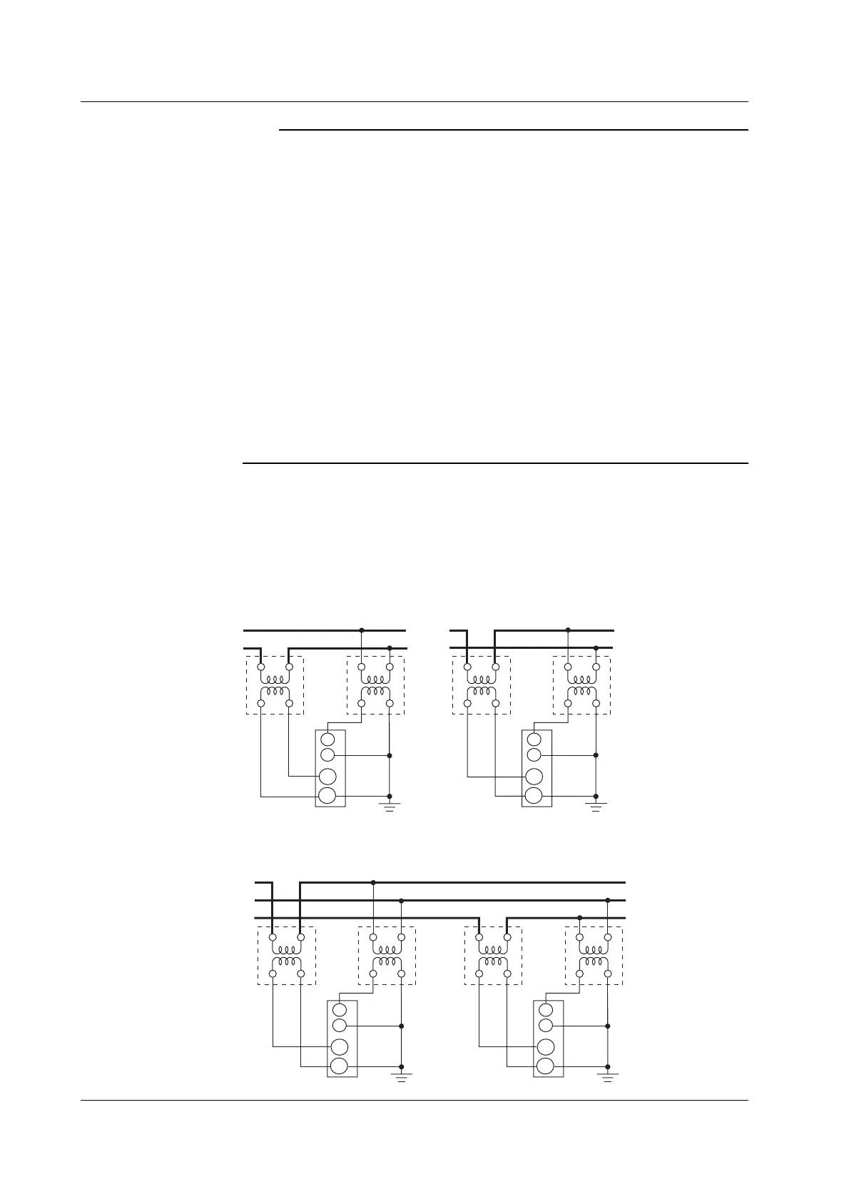
Wiring Example of a Single-Phase, Two-Wire System (1P2W) Using VT and CT
SOURCE
LOAD
L
CT
VT
V
v
l
SOURCE
LOAD
L
CT
VT
V
v
l
Input terminal
I
±
U
±
Input terminal
I
±
U
±
Wiring Example of a Single-Phase, Three-Wire System (1P3W) Using VT and CT
L
CT
VT
V
v
l
L
CT
VT
V
vl
SOURCE
LOAD
N
Input terminal 1
I
±
U
±
Input terminal 2
I
±
U
±
3.11 Wiring the Circuit under Measurement When Using the VT/CT
 Loading...


