9-7
IM WT5000-02EN
Auxiliary input setup screen
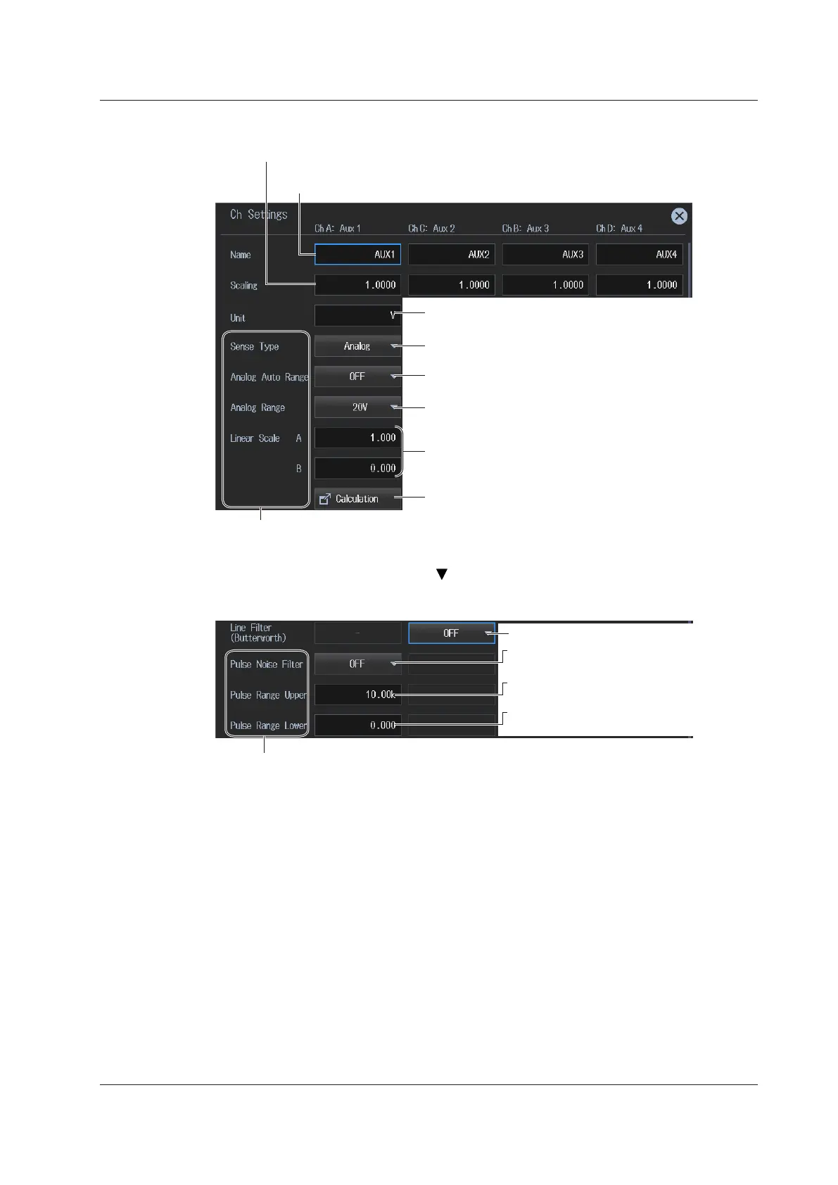
Set the scaling factor (0.0001 to 99999.9999).
Set the scaling factor for scaling or computing auxiliary signals.
Set the unit (up to 8 characters).
Set the auxiliary signal unit.
Set the input signal type (Analog, Pulse).
Set the auxiliary signal type.
Turns auto range on and off
Set the fixed range (20V, 10V, 5V, 2V, 1V).
You can set these when Sense Type is set to Analog.
Set the linear scale
(A: 0.001m to 1.000M and –0.001m to –1.000M,
B: –1.000M to 1.000M).
Set A (the slope) and B (the offset).
Computes A and B
Set the signal name (up to 8 characters).
Set the signal names for Aux1 to Aux4.
Drag the screen to display the bottom area of the setup screen.
Set the line filter (OFF, 1kHz, 500Hz, 100Hz).
1
(Ch A: Aux 1 column)
Set the upper limit of the auxiliary signal
(–10.00M to 10.00M).
You can set these when SenseType is set to Pulse.
(Ch C: Aux 2 column)
(Ch B: Aux 3 column)
(ChD: Aux 4 column)
Set the pulse noise filter
(OFF, 1MHz, 100kHz, 10kHz).
Set the lower limit of the auxiliary signal
(–10.00M to 10.00M).
1 You can set this when SenseType is set to Analog.
9.1 Configuring Motor Evaluation and Auxiliary Input Settings
 Loading...


