9-9
IM WT5000-02EN
Setting the Electrical Angle Measurement (Electrical Angle
Measurement)
Selecting the Harmonic Group (Harmonics Trigger)
5.
Tap ON/OFF under Electrical Angle Measurement. The button changes to ON. The Harmonics
and Correction buttons next to the ON/OFF button become available (step 7).
6.
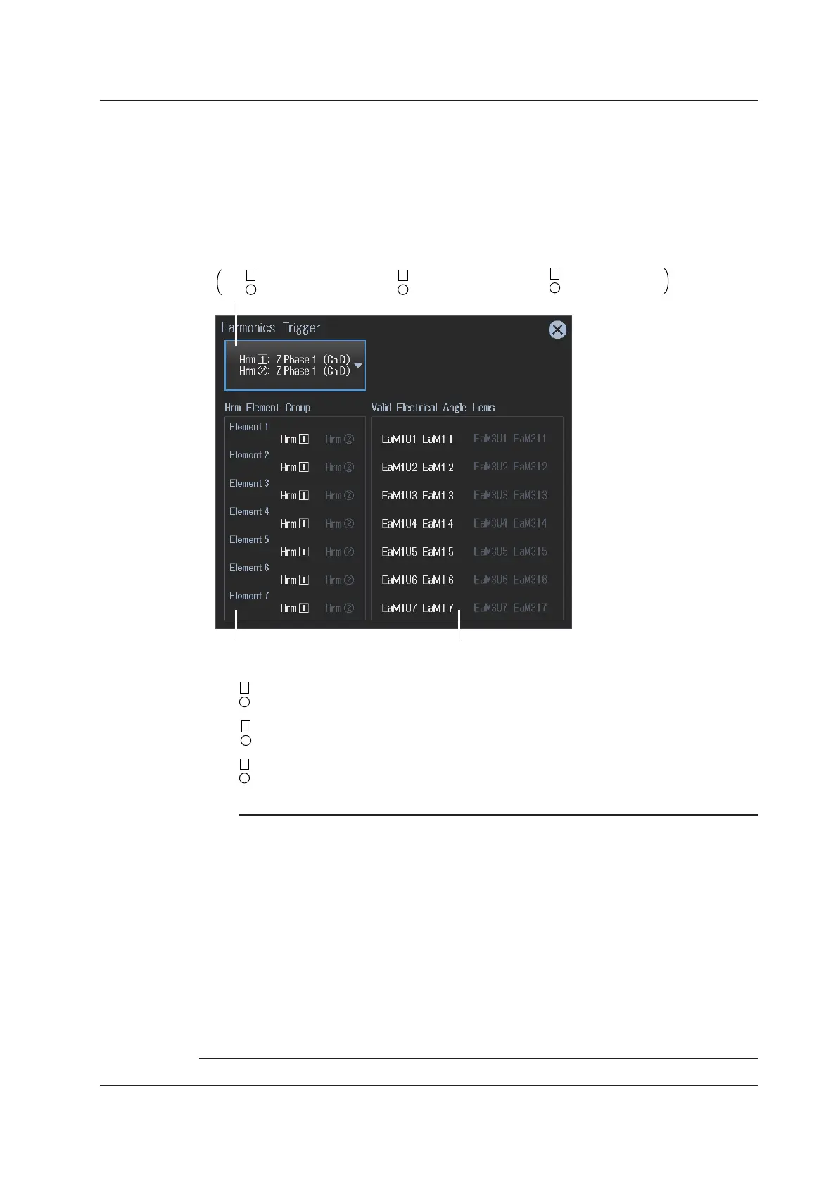
Tap Harmonics Trigger. A Harmonics Trigger screen appears.
Set the harmonic analysis trigger.
Hrm 1 : Z Phase 1 (Ch D)
Hrm
2
: None
Hrm 1 : Z Phase 1 (Ch D)
Hrm
2
: Z Phase 1 (Ch D)
Hrm 1 : None
Hrm
2
: Z Phase 1 (Ch D)
, ,
: Set the Hrm1 trigger to the Z phase of motor 1.
: Set the Hrm1 and Hrm2 triggers to the Z phase of motor 1.
: Set the Hrm2 trigger to the Z phase of motor 1.
Hrm 1 : Z Phase 1 (Ch D)
Hrm
2
: None
Hrm 1 : Z Phase 1 (Ch D)
Hrm
2
: Z Phase 1 (Ch D)
2
Electrical angle measurement items
These are determined and shown
automatically depending on the configuration.
Shows harmonic element grouping
Note
The harmonic analysis trigger parameters vary depending on the /MTR1 option and /MTR2 option.
• Electrical angle measurement of motor 1 set to on and Electrical angle measurement of motor 2
set to off
Hrm1: Z Phase1 and Hrm2: Z Phase1
Hrm1: Z Phase1 and Hrm2: None
Hrm1: None and Hrm2: Z Phase1
• Electrical angle measurement of both motor 1 and motor 2 set to on
Hrm1: Z Phase1 and Hrm2: Z Phase3
Hrm1: Z Phase3 and Hrm2: Z Phase1
• Electrical angle measurement of motor 1 set to off and electrical angle measurement of motor 2
set to on
Hrm1: Z Phase3 and Hrm2: Z Phase3
Hrm1: Z Phase3 and Hrm2: None
Hrm1: None and Hrm2: Z Phase3
9.1 Configuring Motor Evaluation and Auxiliary Input Settings
 Loading...


