SonTek/YSI
ADVField/Hydra Operation Manual (September 1, 2001) 69
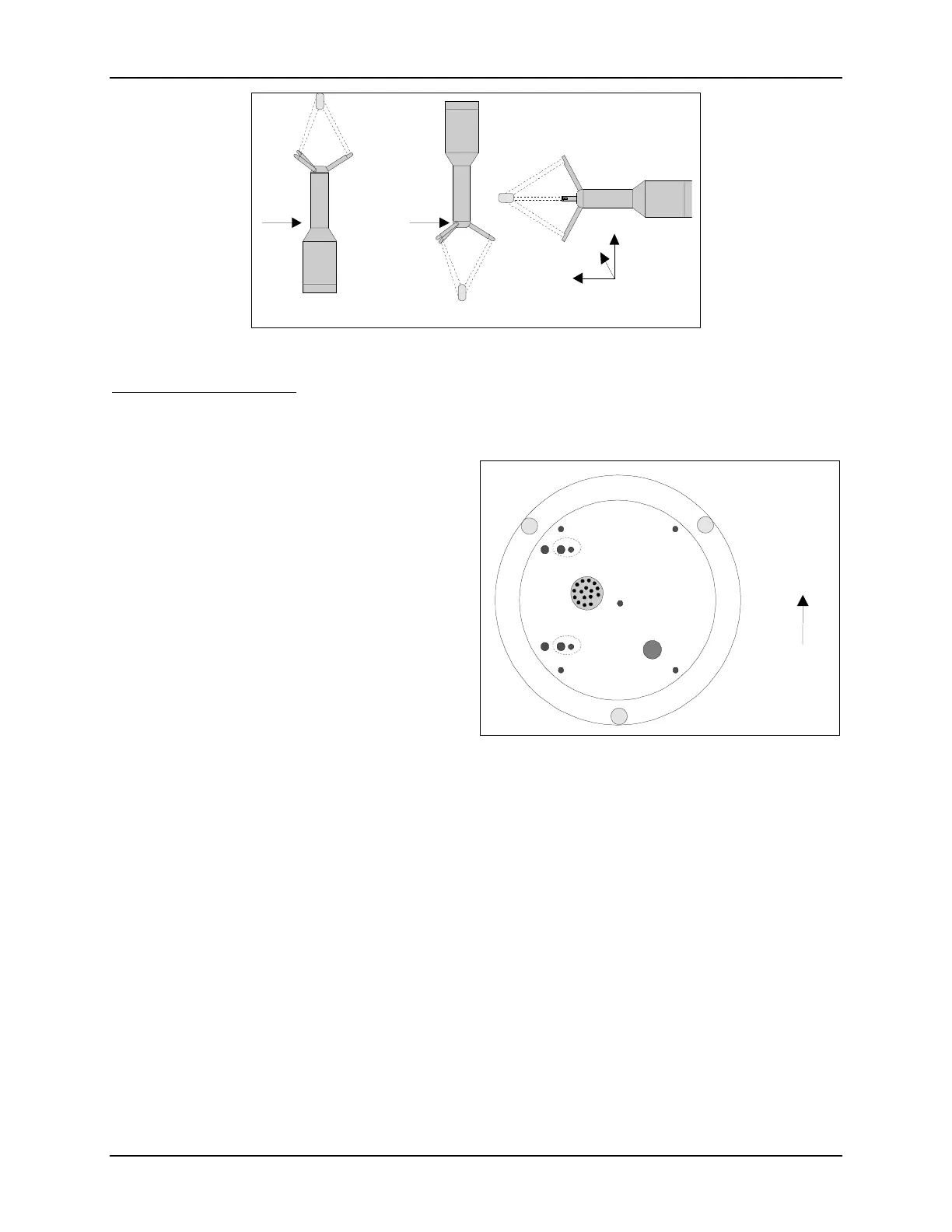
Internal End Cap Design
Figure 18 shows the inside of the conditioning module’s end cap. The items on this end cap will
be referenced when describing compass installation. The three holes around the diameter are for
mounting the end cap to the body of the condi-
tioning module. Near the center of the end cap,
the back of the underwater mateable connector
protrudes slightly with several wires coming
from it. If a pressure sensor is installed, there is
a hole with six wires from this sensor.
The end cap has several drilled and tapped
holes to accommodate the various compass-
mounting arrangements. These holes are di-
vided into three groups, with holes for each
group labeled 1, 2, and 3.
Group 1 consists of four holes with threaded in-
serts for #4-40 bolts. These holes are in a rec-
tangular pattern to match the mounting pattern
of the compass card, and are used for mounting the compass for up or down-looking operation.
Group 2 consists of two holes with threaded inserts for #6-32 bolts; these holes are 1.75" apart.
They match the right-angle mounting bracket used for side-looking compass installation. Group 3
consists of five holes that are not used; these holes are present only in the first production run of
the ADV with compass and tilt sensor.
All mounting holes use self-locking threaded inserts. These inserts give some resistance when
tightening the last portion of the threads. The self-locking inserts are used to prevent loosening
due to vibration and eliminate the need for lock washers.
The three mounting holes that secure the end cap to the body of the conditioning module are
slightly asymmetric; the end cap can only be installed in one direction. This ensures that the
probe X-axis as stamped on the end cap matches the probe X-axis as determined by the orienta-
tion of receiver arm #1. The upper end cap and the position of receiver arm #1 are aligned at the
factory; these should never be modified without first contacting SonTek.
U
Lookin
Down Lookin
Side Lookin
Probe
X
Probe
X
Y
Probe
X
Z
Figure 17 - ADV / ADVOcean Probe Orientations
Probe X
1 1
1
1
2
2
3
3
3
Connector
Pres
Figure 18 - Conditioning Module End Cap

 Loading...


