SonTek/YSI
70
ADVField Operation Manual (September 1, 2001)
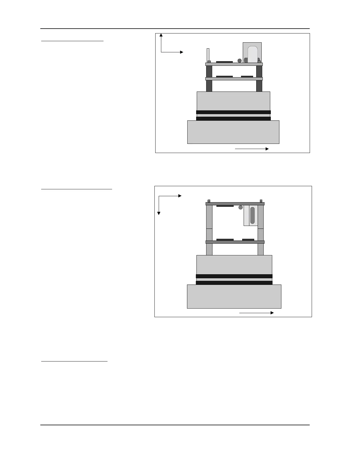
Up-Looking Mounting
Figure 11 shows the compass/tilt sensor
mounted for up-looking operation. The
mounting is in two layers on the end cap
of the conditioning module. Four stand-
offs (
#4-40 x 3/8”
) are screwed into the
end cap (Group 1 holes). The pressure /
temperature sensor is installed on these
standoffs; board orientation does not
matter. Atop this board are four stand-
offs (
#4-40 x 1/2”
). Last, the compass/ tilt
sensor is secured by four screws (
#4-40 x
3/8”
) with fiber washers on each side.
To ensure correct compass data, align
the compass’s positive X-axis (from the
connector to the magnetic coils) with the
probe’s positive X-axis (as stamped on the end cap).
Down-Looking Mounting
Figure 12 shows the compass/tilt sensor
mounted for down-looking operation.
The mounting is in two layers on the end
cap of the conditioning module. Four
standoffs (
#4-40 x 3/8”
) are screwed into
the end cap (Group 1 holes). The pres-
sure/temperature sensor is installed on
these standoffs; board orientation does
not matter. Atop this board are two sets
of standoffs; first are the same standoffs
used for up-looking operation (
#4-40 x
1/2”
), second is a set of longer standoffs
(
#4-40 x 1”
) used to clear the height of
the board components. The compass is
mounted to the last set of standoffs and
secured by four screws (
#4-40 x 3/8”
)
with fiber washers on each side.
To ensure correct compass data, align the compass positive X-axis (from the connector to the
magnetic coils) with the probe positive X-axis (as stamped on the end cap).
Side-Looking Mounting
Figure 21 shows the compass/tilt sensor mounted for side-looking operation. The mounting uses
a right-angle bracket (included in the ADV tool kit). This bracket (already assembled) consists of
two aluminum pieces secured together by #6-32 screws.
The right-angle bracket is secured to the end cap using two #6-32 x 1/2” screws (Group 2 holes).
The compass and pressure/temperature sensor boards are installed in two layers. First, a set of
four standoffs (#4-40 x 3/8”) is attached to the bracket. The pressure sensor is mounted to these
X
Z
Probe X-axis
Compass Axis
Compass/Tilt
Sensor
Pressure / Temp
Sensor Board
3/8" Hex Standoffs
3/8" Hex Standoffs
Figure 19 - Compass/Tilt Sensor Mounting,
Up-Looking
X
Z
Probe X-axis
Compass Axis
Compass/Tilt
Sensor
Pressure / Temp
Sensor Board
3/8" Hex Standoffs
3/8" Hex Standoffs
3/4" Hex Standoffs
Figure 20 - Compass/Tilt Sensor Mounting,
Down Looking

 Loading...


