SonTek/YSI
ADVField/Hydra Operation Manual (September 1, 2001) 71
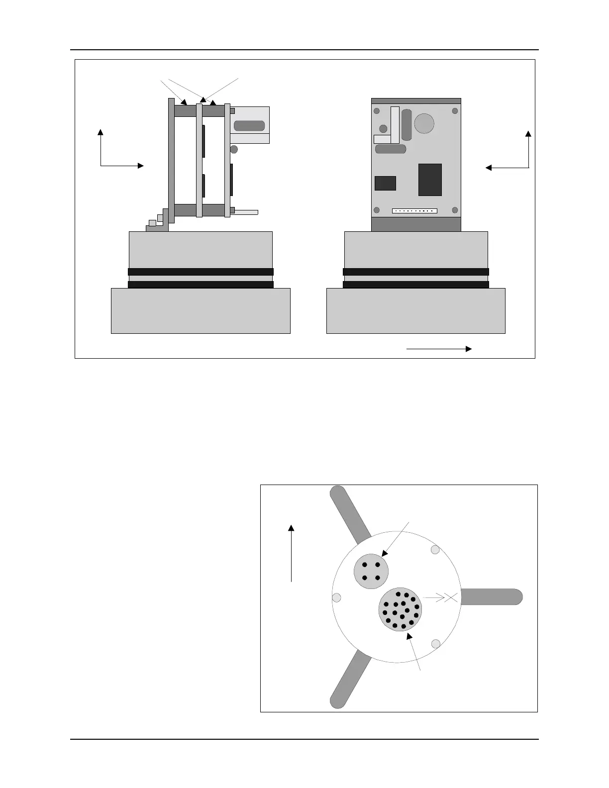
standoffs; board orientation does not matter. Above the sensor board are four standoffs (#4-40 x
1/2”). Last is the compass, secured by four #4-40 x 3/8” bolts, with fiber washers on each side.
Align the compass as shown in Figure 21. For side-looking operation, it is not possible to align
the compass X-axis with the probe X-axis. Instead, the probe X-axis is aligned with the compass
negative Y-axis. Assuming the orientation switch is set for side-looking operation (§4.2), this
alignment is accounted for internally.
In side-looking operation, you must
ensure the probe’s X-axis (stamped
on the end cap and defined by re-
ceiver arm #1) is in the horizontal
plane (within the ±50° limits of the
tilt sensor). When looking at the rear
end cap, the pressure sensor should
be in the position shown in Figure 22.
If the system does not have a pressure
sensor, make sure the X-axis points
to the right of the underwater connec-
tor. Figure 22 shows the orientation.
If the system is not oriented correctly,
the compass will be upside down and
will give invalid data.
Probe X
X
Z
Compass Axis
Compass/Tilt
Sensor
3/8" Hex Standoffs
Pressure
Temp
Sensor Board
X
Y
Compass Axis
Figure 21 - Compass/Tilt Sensor, Side-Looking Mounting
Receiver #1
Vertically Up
Pressure
Underwater
Connector
Figure 22 - Probe Mounting, Side-Looking Compass

 Loading...


