2 - 12 MC67 Integrator Guide
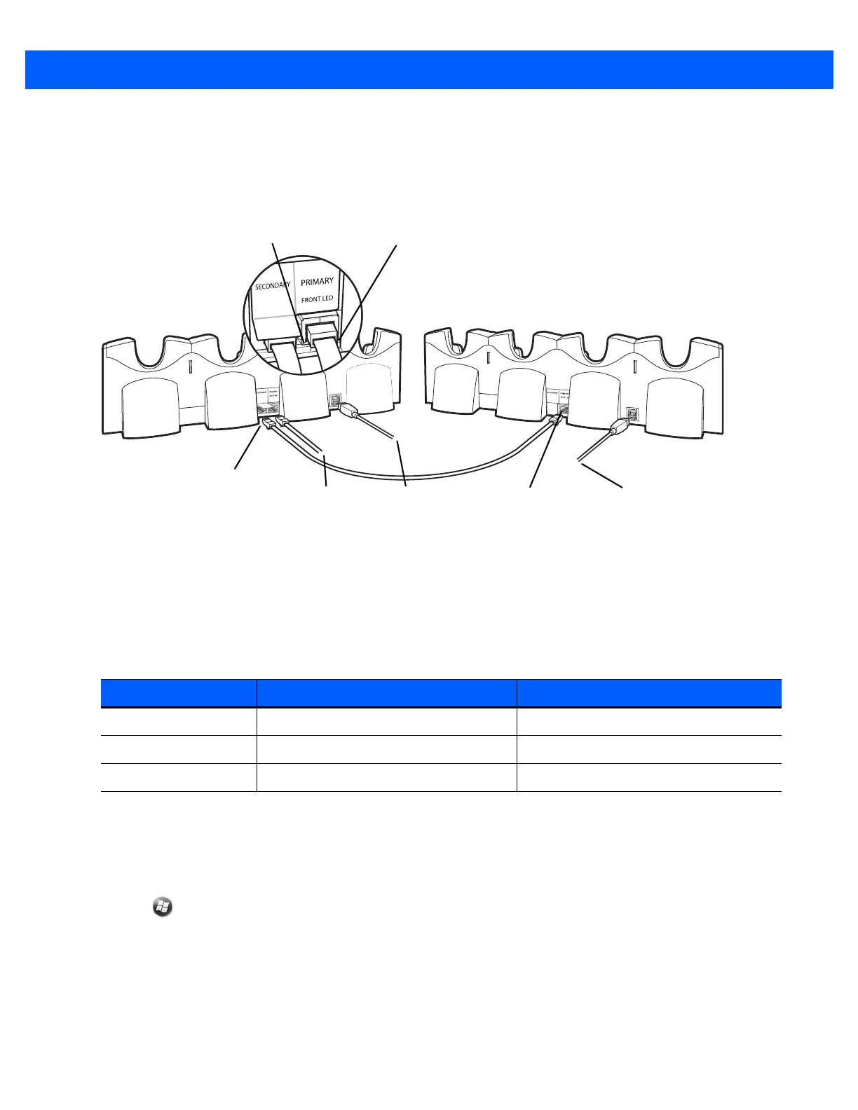
3. On the first Four Slot Ethernet cradle, lift or remove the label flap and connect a second Ethernet cable to
the Secondary Port. See Figure 2-11.
4. Connect the other end of the Ethernet cable to the Primary Port of the second Four Slot Ethernet cradle.
5. Connect additional cradles as described in step 3 and 4.
Figure 2-11
Daisychaining Four Slot Ethernet Cradles
LED Indicators (CRD5501-4001ER)
There are two green LEDs on the front of the cradle and two green LED on the Primary port on the back of the
cradle. These green LEDs light and blink to indicate the data transfer rate. When the LEDs are not lit the
transfer rate is 10 Mbps.
Ethernet Cradle Drivers
The MC67 includes Ethernet cradle drivers that initiate automatically when you place the MC67 in a properly
connected Four Slot Ethernet cradle. After inserting the MC67, configure the Ethernet connection:
1. Tap > Settings > Connections tab >WiFi icon. The Configure Network Adapters window appears.
Table 2-4
CRD5501-4001ER LED Indicators
Data Rate Left 1000 LED (Green) Right 100 LED (Green)
1 Gbps On/Blink Off
100 Mbps Off On/Blink
10 Mbps Off Off
To S w i tch
Secondary Port
Right LEDLeft LED
Primary PortTo Power Supply To Power Supply